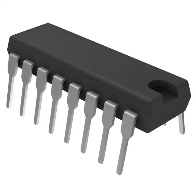
Quad SPST-NC analog switch in a 16-DIP package
Each of the four switches is a 1:1 multiplexer/demultiplexer circuit, meaning it connects or disconnects a single signal path per channel. The normally-closed configuration means the switch is closed (conducting) when the control input is at logic low, and opens when driven high — a detail that matters for fail-safe signal routing in instrumentation and control loops.
On-resistance and signal integrity
The on-state resistance is 3.5 kOhm maximum — relatively high compared to modern CMOS switches (which often sit below 100 Ohm). That 3.5 kOhm series resistance will attenuate the signal and interact with load impedance; plan for it in the gain budget of the downstream amplifier or ADC driver. Channel-to-channel matching is 175 Ohm maximum, so the four channels track reasonably well but not tightly enough for precision gain-matching without calibration. Crosstalk is -90 dB at 100 kHz. Charge injection is 2 pC typical. Leakage current is 10 pA maximum off-state. Channel capacitance is 1.7 pF each side.
The dual-supply option lets the switch handle bipolar signals (audio, instrumentation) without level-shifting. Switching times are 1 µs turn-on and 500 ns turn-off maximum. That is fast enough for audio muting, relay replacement, or low-speed multiplexing at audio frequencies, but not for video switching or high-speed data routing.
The 16-DIP package (0.300-inch row spacing, 7.62 mm) with through-hole leads is breadboard-friendly and easy to hand-solder or socket. The supplier device package is 16-PDIP. The tube shipping medium is standard for DIP parts — no reel or tray concerns for prototyping or low-volume production.