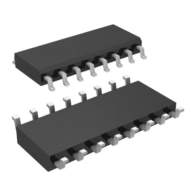
Analog Devices MAX14932BASE+ — Digital Isolators

MAX14932BASE+ General Purpose Digital Isolator, 4-Ch, 25Mbps

MPNMAX14932BASE+
End of Life

Maxim Integrated MAX14932BASE+, General Purpose digital isolator, 4 channels, 25Mbps data rate, capacitive coupling, 2750Vrms isolation, 16-SOIC package, -40°C to 125°C.

$5.67Ref. price · indicative, final on quote
Packaging16-SOIC (0.154", 3.90mm Width)
RoHSROHS3 Compliant
Independent supplier — new & surplus stockAuthenticity-screened · ESD-safe packingListing updated Aug 2026

Specifications

MAX14932BASE+ specifications
ParameterValue
TypeGeneral Purpose
Channel typeUnidirectional
MountingSurface Mount
Supply voltage1.71V ~ 5.5V
Voltage - isolation2750Vrms
Isolated powerNo
Operating temperature-40°C ~ 125°C
Pulse width distortion2.6ns
PackageTube
Data rate25Mbps
TechnologyCapacitive Coupling
Case16-SOIC (0.154\", 3.90mm Width)
Channels4
Inputs - side 1/Side 22/2
Rise (Fall time)2ns, 2ns
Propagation delay tpLH (tpHL)27.5ns, 28.8ns
Common mode transient immunity25kV/µs (Typ)

Product details

It provides galvanic isolation up to 2750Vrms between two sides of a circuit, with a data rate of 25Mbps. Typical applications include isolating SPI, UART, or general-purpose digital signals in industrial automation, motor drives, power supplies, and medical equipment where noise immunity and safety isolation are required.

The 25Mbps data rate handles most common serial interfaces. The 2750Vrms isolation rating is typical for reinforced isolation in industrial environments.

Frequently asked questions

Is MAX14932BASE+ RoHS compliant?

Yes, the MAX14932BASE+ is ROHS3 compliant.

Can MAX14932BASE+ be used for I2C isolation?

I2C is a bidirectional open-drain bus, and the MAX14932BASE+ has unidirectional channels. For I2C isolation you need a part with bidirectional channels or external circuitry to handle the bus direction. This part is better suited for SPI, UART, or GPIO isolation.

What is the pinout of MAX14932BASE+?

The pinout follows the standard 16-SOIC layout for Maxim's 4-channel isolators. Side 1 inputs are on pins 2 and 3; side 2 inputs on pins 10 and 11. Outputs are on the opposite sides. Refer to the datasheet for the full pin map.