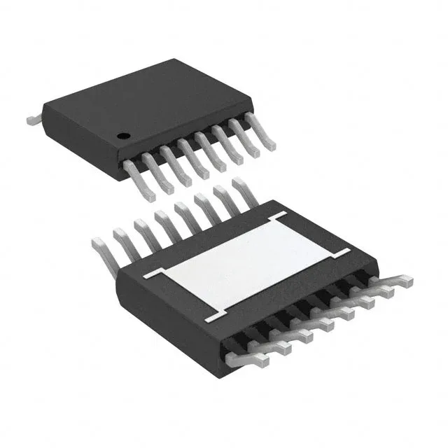
Boost controller with synchronous rectification for battery-to-rail conversion
The LTC7804IMSE#PBF is a low quiescent current synchronous boost controller from Analog Devices, designed for step-up (boost) conversion from a 4.5V to 40V input rail. Its 100% maximum duty cycle allows pass-through operation when the input voltage exceeds the target output, a useful feature for battery-powered systems where the input sags below the regulated rail. The controller drives external N-channel MOSFETs in a synchronous rectifier configuration, which improves efficiency over a diode-based boost by recovering the forward-drop loss. This matters for designs where every percent of efficiency extends battery runtime — think portable instruments, automotive pre-boost stages, or industrial sensor nodes running from a 12V or 24V bus. Switching frequency is programmable from 100kHz to 3MHz via a single resistor, letting the designer trade off inductor size against switching losses. At the low end, larger magnetics but better efficiency; at the high end, a smaller footprint but more heat in the FETs and controller.
Package, thermal, and layout notes for the 16-MSOP-EP
Housed in a 16-lead MSOP with an exposed pad (16-MSOP-EP), the LTC7804IMSE#PBF requires a thermal land on the PCB to sink heat from the die. The exposed pad is the main thermal path — without a proper via array to a copper plane, the junction temperature rises quickly under continuous load, especially at higher switching frequencies. Shipped in a Tube, not tape-and-reel — plan for manual or low-volume pick-and-place. If your line runs high-volume reels, factor in a tube-to-reel transfer or order the tape-and-reel variant if one exists.
Active lifecycle and compliance — no end-of-life pressure
RoHS3 compliant (RoHS exemption status not specified beyond the compliance statement), which covers EU and most global BOM requirements without the need for an exemption review.
How it compares to the LTC3814EFE-5#PBF boost controller
The closest functional peer in the ledger is the LTC3814EFE-5#PBF. Both are synchronous boost controllers with a single output, positive configuration, and transistor-driver output. The LTC3814 adds control features (Enable, Power Good, Soft Start) that the LTC7804 does not list in its spec table — if your design relies on a dedicated Power Good flag or a sequenced soft-start, the LTC3814 may be a better fit. The LTC7804's supply range (4.5V to 40V) matches the LTC3814's (4.35V typical), and both operate over the same -40°C to 125°C junction temperature range. The LTC7804's switching frequency range (100kHz to 3MHz) is wider than the LTC3814's fixed-frequency options, giving more flexibility for inductor selection. Package difference: the LTC7804 comes in 16-MSOP-EP, while the LTC3814EFE-5#PBF uses a 20-TSSOP-EP. The pinout and footprint are not compatible — a board spin is required to swap between them.