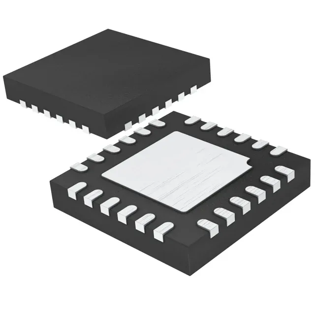
Buck controller with synchronous rectification
The LTC3866EUF#PBF: The synchronous rectifier improves efficiency by replacing the freewheeling diode with a second FET, cutting conduction losses in the low-side path — important for high-current POL rails where every millivolt of dropout costs thermal headroom. It operates from a 4.5V to 38V supply (Vcc/Vdd), which covers common intermediate bus rails (5V, 12V, 24V) and industrial supplies up to 36V nominal. The switching frequency is programmable from 250kHz to 770kHz via a resistor on the RT pin — lower frequency cuts switching losses for heavy loads; higher frequency shrinks the inductor and output cap but pushes more loss into the FET gate drive. The controller outputs a transistor driver signal — it does not integrate the power FETs, so the external MOSFET pair must be selected for the target load current and input voltage.
Control features and rework note
The LTC3866EUF#PBF includes current limit, enable, frequency control, power good, soft start, and tracking. The tracking feature allows the output to follow an external reference ramp during startup — useful for sequencing multiple rails in an FPGA or ASIC power tree where the core must not rise before the I/O. Soft start limits inrush current; the power-good flag can drive a reset or enable the next converter in the sequence. The 24-QFN (4x4 mm) is a standard QFN with a centre pad — the pad is the main thermal path and the ground return for the gate-drive loop. The pin 1 corner is marked by a chamfer on the package body, visible under a microscope. The exposed pad sits flush with the bottom of the package; a stencil aperture of 50-60% of the pad area keeps solder from wicking up the sides and shorting to the thermal land vias. The part is ROHS3 compliant, so the solder balls are lead-free — reflow profile follows the standard SAC305 curve with a peak around 245°C.