Buck-boost controller with synchronous rectification
The LTC3789EUFD#PBF is a current-mode buck-boost controller that regulates a positive output voltage from an input that can be above, below, or equal to the output. It drives two sets of external N-channel MOSFETs — one pair for the buck stage, one for the boost stage — and integrates the synchronous rectifier drivers so you skip the catch diode entirely. Supply range is 4V to 38V (Vcc/Vdd), which covers 12V and 24V industrial rails, automotive battery lines through crank and load-dump, and battery-backed systems from 4-cell Li-ion up. Switching frequency is programmable from 200kHz to 640kHz via a single resistor on the RT pin — no external clock sync. Higher frequencies shrink the inductor and output capacitor, lower frequencies improve efficiency at heavy load.
Thermal and package constraints for the layout
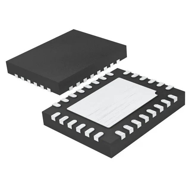
The 28-QFN (4x5 mm) exposed pad package requires a solid thermal connection to the PCB ground plane. The limiting factor becomes the MOSFETs and inductor — their temperature ratings set the real ceiling.
Control features that simplify the BOM
On-chip control features include current limit, enable, frequency control, power good, and soft start. The soft-start pin lets you ramp the output voltage gradually, preventing inrush current from tripping the upstream supply. Maximum duty cycle is 90%, which limits the step-down ratio at low input voltages. For a 5V output from a 6V input, the 90% ceiling is comfortable — but a 3.3V output from a 4V input pushes the duty cycle close to the limit, leaving little margin for transient drop.
Surface-mount 28-QFN (4x5 mm).