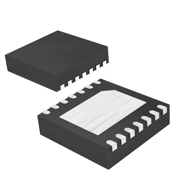
Analog Devices DS1344D-3+T&R — DC-DC Power Modules

DS1344D-3+T&R RTC Clock/Calendar, SPI, 96B NVRAM, 14-TDFN

MPNDS1344D-3+T&R
End of Life

Maxim Integrated DS1344D-3+T&R, Clock/Calendar RTC, SPI, 96B NVRAM, Alarm, Trickle Charger, 2.7V-5.5V, -40°C~85°C, 14-TDFN (3x3), Tape & Reel.

$6.21Ref. price · indicative, final on quote
Packaging14-WFDFN Exposed Pad
RoHSROHS3 Compliant
Independent supplier — new & surplus stockAuthenticity-screened · ESD-safe packingListing updated Aug 2026

Specifications

DS1344D-3+T&R specifications
ParameterValue
TypeClock/Calendar
MountingSurface Mount
Voltage2.7V ~ 5.5V
Voltage - supply, battery1.3V ~ 5.5V
InterfaceSPI
Operating temperature-40°C ~ 85°C
PackageTape & Reel (TR); Cut Tape (CT)
FeaturesAlarm, Leap Year, NVRAM, Square Wave Output, Trickle Charger
Date formatYY-MM-DD-dd
Memory size96B
Time formatHH:MM:SS (12/24 hr)
Case14-WFDFN Exposed Pad

Product details

SPI bus and trickle-charger — integration notes

The SPI interface keeps the pin count low — four wires (SCLK, MOSI, MISO, CS) plus the interrupt/alarm output. The trickle charger is a series diode and current-limiting resistor network that charges a backup battery or supercap from the main VCC; the datasheet shows the selectable resistor values. The square-wave output can drive a microcontroller interrupt or a status LED without an external transistor. The 96-byte NVRAM is accessed over the same SPI bus and retains data as long as the backup supply is present.

There is no NRND or last-time-buy notice on this part.

Frequently asked questions

What does the DS1344D-3+T&R datasheet specify?

The datasheet specifies a real-time clock/calendar with SPI interface, 96 bytes of NVRAM, alarm, leap-year compensation, square-wave output, and a trickle charger. It operates from 2.7V to 5.5V main supply with a separate battery input from 1.3V to 5.5V, over -40°C to 85°C, in a 14-TDFN (3x3 mm) package.

Is there a drop-in replacement or equivalent for DS1344D-3+T&R?

Maxim does not list a direct pin-compatible second source for this exact order code. The DS1344 family shares the same SPI interface and feature set across density options; verify the specific package (14-TDFN) and temperature grade before substituting.

How do I connect DS1344D-3 to a microcontroller?

Connect the SPI pins (SCLK, MOSI, MISO, CS) to the microcontroller's SPI bus. Provide a 2.7V to 5.5V supply on VCC and a backup battery on VBAT. The exposed pad on the 14-TDFN package should be soldered to the PCB ground plane for thermal management.