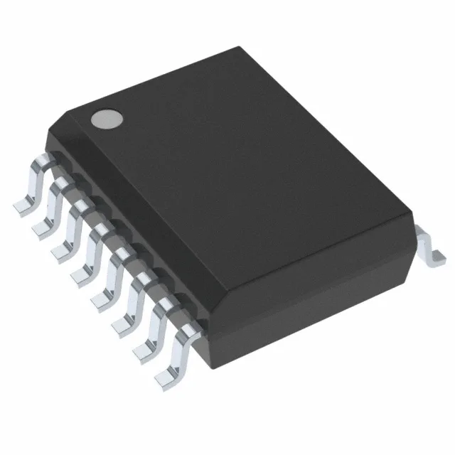
What this isolated gate driver delivers on the board
The Analog Devices ADUM4223BRWZ-RL is a dual-channel isolated gate driver from the iCoupler family, built around magnetic coupling technology. It provides 5000 Vrms galvanic isolation between the input logic and the two output channels, each rated for 4 A peak drive current. The output supply range of 7.5 V to 18 V covers the standard gate-drive voltages for silicon MOSFETs and IGBTs.
The 4 A peak output current is the figure that determines how fast the driver can charge the gate capacitance of the switching device. For a typical MOSFET with 10 nC of gate charge at 12 V, the 4 A peak translates to a rise time around 2.5 ns at the gate node, though the 12 ns typical rise/fall time in the datasheet accounts for the internal driver stage and package parasitics. The 54 ns max propagation delay is symmetric (tpLH = tpHL), which simplifies dead-time calculation in complementary-switch topologies — you budget the same delay on both edges. The 50 kV/µs CMTI rating means the driver rejects common-mode transients up to that slew rate without corrupting the output. In a motor-drive inverter where the switching node sees dV/dt of 10–20 kV/µs, this part provides margin. The output supply range from 7.5 V to 18 V allows the same driver to work with logic-level MOSFETs at 8 V or standard IGBTs at 15 V.
ROHS3 compliant.
Cut Tape quantities are also available for prototyping.