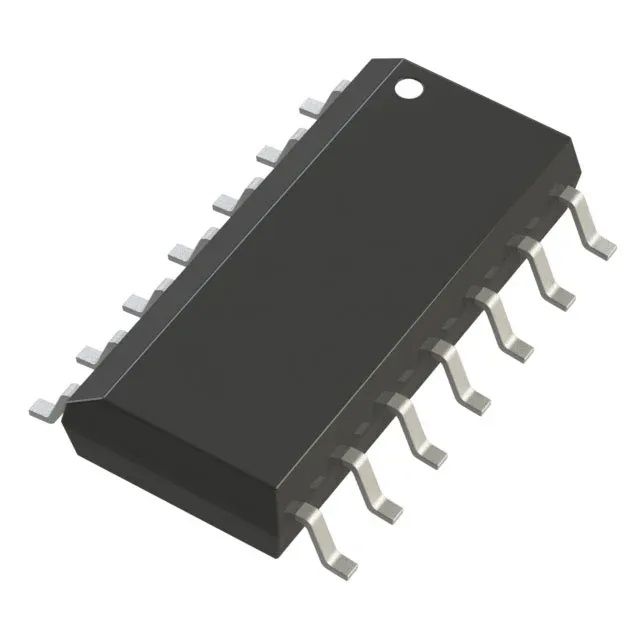
Analog Devices AD8604ARZ-REEL — Analog & Data Acquisition

AD8604ARZ-REEL Quad CMOS Op-Amp, 8.4 MHz, Rail-to-Rail

MPNAD8604ARZ-REEL
End of Life

ADI DigiTrim® series, AD8604ARZ-REEL, CMOS quad op-amp, 8.4 MHz gain bandwidth, 6 V/µs slew rate, rail-to-rail output, 2.7 V to 5.5 V supply, 750 µA per channel, 14-SOIC package, -40°C to 125°C.

$3.64Ref. price · indicative, final on quote
Packaging14-SOIC (0.154", 3.90mm Width)
RoHSROHS3 Compliant
SeriesDigiTrim®
Independent supplier — new & surplus stockAuthenticity-screened · ESD-safe packingListing updated Aug 2026

Specifications

AD8604ARZ-REEL specifications
ParameterValue
SeriesDigiTrim®
Output typeRail-to-Rail
MountingSurface Mount
Amplifier typeCMOS
Voltage - input offset80 µV
Voltage - supply span5.5 V
Current - supply750µA (x4 Channels)
Current - input bias0.2 pA
Current - output (Channel)50 mA
Operating temperature-40°C ~ 125°C
Gain bandwidth product8.4 MHz
PackageTape & Reel (TR); Cut Tape (CT)
Slew rate6V/µs
Case14-SOIC (0.154\", 3.90mm Width)
Number of circuits4

Product details

The 8.4 MHz gain-bandwidth product sets the usable closed-loop bandwidth. The 6 V/µs slew rate keeps large-signal distortion low. Input offset voltage is 80 µV maximum. Input bias current is 0.2 pA. Output current per channel is 50 mA.

Minimum supply is 2.7 V, maximum is 5.5 V. Rail-to-rail output simplifies single-supply ADC interface.

Frequently asked questions

What is the equivalent for AD8604ARZ-REEL?

The AD8604ARUZ (TSSOP-14) and AD8604ARQZ (QSOP-16) are electrically identical siblings with the same 8.4 MHz GBW, 6 V/µs slew rate, and quad CMOS architecture, differing only in package and tube vs. tape-and-reel delivery. For a single-channel alternative, the AD8605ACBZ-REEL7 offers 10 MHz GBW in a smaller package.

What is the pinout of AD8604ARZ-REEL?

The AD8604ARZ-REEL uses the standard 14-SOIC quad op-amp pinout: output 1 on pin 1, inverting input 1 on pin 2, non-inverting input 1 on pin 3, V+ on pin 4, non-inverting input 2 on pin 5, inverting input 2 on pin 6, output 2 on pin 7, output 3 on pin 8, inverting input 3 on pin 9, non-inverting input 3 on pin 10, V- on pin 11, non-inverting input 4 on pin 12, inverting input 4 on pin 13, output 4 on pin 14.