133.333 MHz MEMS XO — frequency, stability, and the Enable/Disable function
The ASEMPC-133.333MHZ-LY-T3: That frequency is a 1/12 divisor of the 1.6 GHz USB-PLL reference commonly used in USB 2.0 full-speed host controllers and USB-C CC-logic PHYs — the exact divisor means no rounding error in baud-rate generation. The Enable/Disable function on pin 1 lets the host MCU gate the output without removing power from the device — disabled the oscillator draws a maximum of 26 mA versus 35 mA active, so a sleep-mode design that toggles the OE pin saves real current rather than relying on the device's power-rail draw alone.
Supply rail and power budget
At 35 mA maximum the CMOS output drive is sized for a short PCB trace to a clock input; if the trace runs more than a few centimetres to a connector, add a series termination resistor to damp reflections and keep the edge integrity clean.
6-SMD package and PCB layout checklist
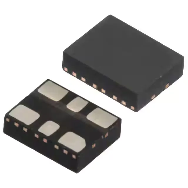
The 3.20 × 2.50 mm housing stands 0.90 mm tall — the low profile matters in thin-form-factor boards where the oscillator must clear the chassis or a heat spreader above the PCB. Solder pad layout follows the manufacturer's recommended footprint for the 6-SMD no-lead format: the exposed paddle under the body ties to the ground net and provides the primary thermal path, so it must reflow with a reliable fillet on the pad — not just rely on paste-through-hole wicking. Because this is a MEMS resonator packaged as an XO, it is more tolerant of mechanical shock and board flex than a traditional crystal-packaged oscillator — the silicon resonator sits inside the IC package, not as a freestanding crystal blank that can crack under drop or sustained vibration.