What this opto does on the board
The Vishay SFH6186-2 is a single-channel phototransistor optocoupler in a 4-SMD gull-wing package, rated for 5300Vrms isolation. It takes a DC input on the LED side and switches a phototransistor on the output side, with a current transfer ratio (CTR) binned at 63% to 125% when the forward current is 1 mA. That CTR window is what you use to calculate the LED drive current needed to guarantee a logic-level output at the load. The part is specced across -55 to 100°C, so it fits industrial and some telecom environments where the board sees temperature swings but not extended engine-bay heat.
5300Vrms isolation — what it buys you
The 5300Vrms isolation rating is the figure a safety engineer checks first. That rating is a one-minute hipot test value; in continuous service the working voltage is lower, but the 5300Vrms mark tells you this part passed the reinforced-insulation test per IEC 60747-5-5. For a 230VAC line application, that margin is comfortable.
CTR bin -2: what it means for a swap
The -2 suffix in SFH6186-2 is the CTR bin: 63% minimum, 125% maximum at 1 mA forward current. That is a tighter spread than the -1 bin (which runs lower) and looser than the -3 or -4 bins. If your BOM calls for the -2, the CTR range is the parameter that sets the LED current and the pull-up resistor on the output. Swapping in a different bin without adjusting the drive will either under-drive the output or saturate the transistor harder than needed. The -2 is a common middle bin for general-purpose isolation where you want a predictable on-state voltage across temperature.
That means it is still a normal production line at Vishay — no last-time-buy notice, no end-of-life clock. The ROHS3 compliance also clears it for markets that enforce the latest EU RoHS exemption rules.
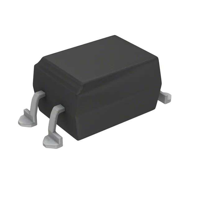
The 4-SMD gull-wing package is a surface-mount footprint, not a through-hole DIP. That means the board gets a reflow profile, not a wave-solder step. The gull-wing leads are visible for inspection after soldering, which helps in prototype builds and rework. If you are replacing a DIP-4 through-hole part, this will not drop in without a board layout change.