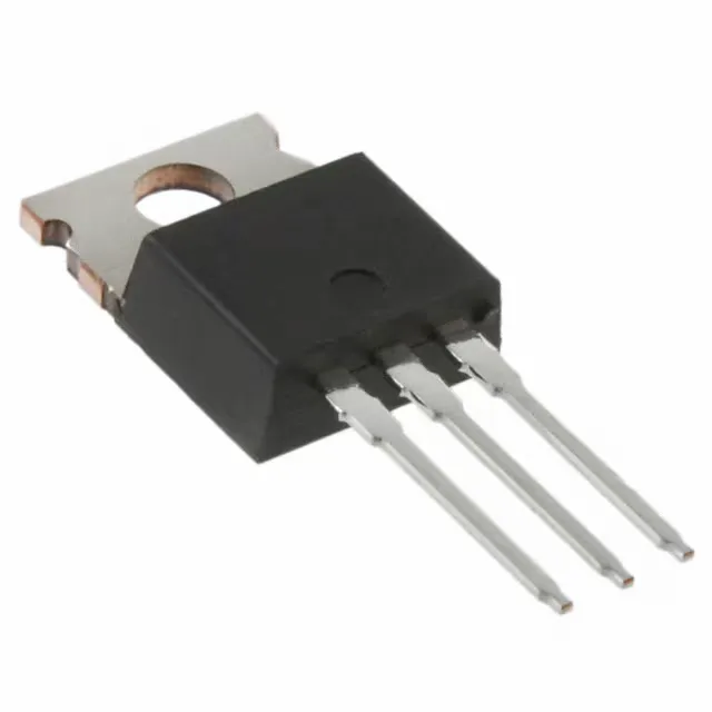
Vishay IRF830APBF

IRF830APBF N-Channel MOSFET, 500 V, 5 A, TO-220AB

MPNIRF830APBF
End of Life

Vishay IRF830APBF, N-Channel MOSFET, 500 Vdss, 5 A Id, 1.4 Ohm Rds(on) at 10 V, 24 nC Qg, TO-220AB through-hole, -55 to 150 °C.

$1.6Ref. price · indicative, final on quote
PackagingTO-220-3
StockContact for availability
MOQ1 pcs
  • 100% new & originalTraceable channels only — no refurbs, no pulls, no remarked parts.
  • Date & lot codes on quoteStated per line before you commit; label photos on request.
  • MSL-compliant ESD packingMoisture-sealed bags with indicator cards; reels photo-verified.
  • PayPal buyer protectionPay by T/T, PayPal or Payoneer — card payments covered end to end.

Specifications

IRF830APBF Technical Specifications
ParameterValue
FET typeN-Channel
Mounting typeThrough Hole
Drain to source voltage500 V
Drive voltage (Max rds on, min rds on)10V
Current - continuous drain (Id) @ 25°C5A (Tc)
Power dissipation74W (Tc)
Operating temperature-55°C ~ 150°C (TJ)
PackageTube
Vgs±30V
TechnologyMOSFET (Metal Oxide)
CaseTO-220-3
Vgs(th) (Max) @ id4.5V @ 250µA
Rds on (Max) @ id, vgs1.4Ohm @ 3A, 10V
Gate charge (Qg) (Max) @ vgs24 nC @ 10 V
Input capacitance (Ciss) (Max) @ vds620 pF @ 25 V

Product details

500 V N-channel in a TO-220AB — where it fits

The IRF830APBF is a 500 V, 5 A N-channel power MOSFET in the through-hole TO-220AB package, built on planar MOSFET technology. It targets offline AC-DC converters, PFC boost stages, and 48 V telecom brick supplies where the 500 V drain-source rating provides adequate margin for universal-input flyback designs.

Rds(on) and gate charge — sizing the drive and heatsink

Maximum on-resistance is 1.4 Ohm at 3 A drain current with a 10 V gate drive. At the full 5 A continuous drain rating, conduction loss reaches I²R = 35 W — well within the 74 W package dissipation limit at the case, but the designer must derate for ambient temperature and heatsink thermal resistance. Total gate charge is 24 nC at 10 V. A typical gate-driver IC sourcing 1 A peak can switch this MOSFET in under 30 ns, keeping the switching transition within the safe-operating area for hard-switched topologies up to about 100 kHz.

Temperature range and package — board-level fit

The junction temperature range spans -55 °C to 150 °C, suiting the part for industrial and telecom environments where the ambient may reach 85 °C and the heatsink runs hot. The TO-220AB lead form matches the standard 0.100-inch pitch hole pattern on a 2-layer PCB; the metal tab requires electrical isolation or a shared drain node.

Frequently asked questions

Is the IRF830APBF the same as the IRF830?

The IRF830APBF is the ROHS3-compliant, lead-free version of the base IRF830. The electrical ratings — 500 Vdss, 5 A Id, 1.4 Ohm Rds(on) — are identical. The 'PBF' suffix indicates the part is fully ROHS3 compliant.

What is the Rds(on) of the IRF830APBF?

This is the conduction loss figure used for thermal and efficiency calculations.

Are there cross-reference or replacement parts for the IRF830APBF?

The IRF830APBF-BE3 is a functional equivalent with the same 500 V, 5 A, 1.4 Ohm ratings and the same TO-220AB package. The IRF830ALPBF is a surface-mount D2PAK variant of the same die; it shares all electrical specs but requires a different PCB footprint.