5300 Vrms isolation — the barrier spec that decides fit
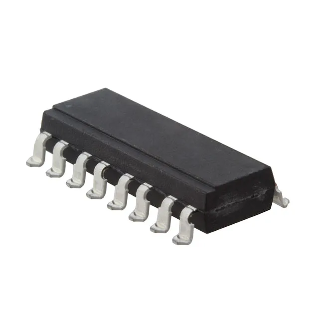
The ILQ74-X009T is a Vishay quad-channel phototransistor optocoupler in a 16-SMD gull-wing package. Its headline rating is 5300 Vrms isolation between input and output — a figure that qualifies it for reinforced insulation in industrial motor drives, medical patient-contact interfaces, and power-supply feedback loops where a single fault must not create a shock hazard. The four independent channels share a common LED-side and detector-side, so one package replaces four single-channel isolators, saving board area and placement cost.
3 µs switching — slow but deliberate
Typical turn-on and turn-off times are both 3 µs. That puts this part squarely in the low-frequency isolation space — think DC signal detection, 50/60 Hz line monitoring, relay replacement, or slow digital I/O. It will not handle high-speed comms (CAN, SPI, Ethernet) or gate-drive waveforms; for those you need a digital isolator or a faster optocoupler family. The 3 µs symmetry is useful: the output waveform stays roughly square, so timing margins in a slow loop are predictable.
12.5% minimum CTR — plan the LED drive
The minimum current transfer ratio is 12.5% at 16 mA forward current. That means with 16 mA through the LED, the output transistor can sink at least 2 mA (12.5% of 16 mA). In practice, CTR degrades with temperature and over the life of the part — the typical CTR is higher, but the minimum is what you design to for guaranteed saturation across the -55°C to 100°C range. The forward voltage is 1.3 V typical, and the absolute maximum forward current is 60 mA, so there is headroom to overdrive the LED if the application demands higher output current at the cost of LED lifetime.