5000 Vrms isolation — the safety barrier spec
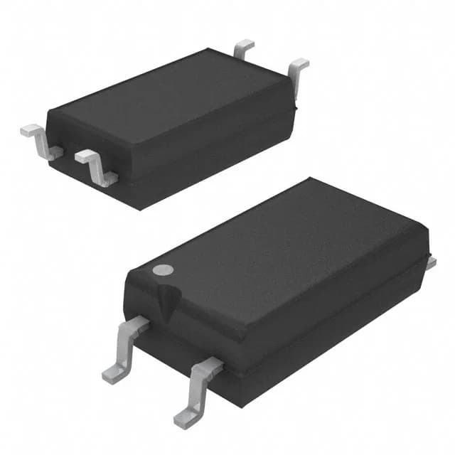
The Toshiba TLP385(D4GL-TR,E is a single-channel, DC-input, transistor-output optocoupler in a compact 4-lead 6-SOIC package (4.40 mm width). Its headline rating is 5000 Vrms of isolation between input and output — the figure that decides whether this part can sit on a mains-referenced secondary side, in a medical patient-contact interface, or across an industrial 24 V to 480 V barrier. The 5000 Vrms rating puts it in the reinforced-isolation class for many applications, though the system-level creepage and clearance still need a PCB layout review.
CTR spread: 50% to 600% at 5 mA — budgeting the LED drive
The current transfer ratio spans 50% minimum to 600% maximum, both specified at a forward current of 5 mA. That 12:1 spread is the single biggest design variable. For the BOM engineer: the minimum CTR of 50% at 5 mA means the output transistor can sink at least 2.5 mA when the LED is driven at 5 mA — that sets the pull-up resistor and the minimum load the output side can drive. The 600% maximum means at the same 5 mA input, the output could sink up to 30 mA, so the collector resistor must be sized to keep Vce below 300 mV saturation at the worst-case high CTR. The 80 V output rating gives headroom for 24 V or 48 V industrial rails.
Temperature range: -55°C to 110°C — industrial and cold-start environments
Rated for -55°C to 110°C operating, this optocoupler covers cold-crank conditions in outdoor telecom cabinets, unheated enclosures in northern climates, and the internal ambient of a motor drive or power supply where the board runs hot. The 110°C upper limit is a practical ceiling for industrial control without stepping to a 125°C-rated part. The 50 mA absolute-maximum forward current and 50 mA output current per channel are typical for a signal-level isolator — not a power relay driver, but fine for PLC digital inputs, isolated I2C, and status LED feedback.
Switching speed and timing
Rise time is 2 µs typical, fall time 3 µs typical; turn-on and turn-off times are both 3 µs typical. These numbers tell you this is a general-purpose optocoupler for 50/60 Hz line synchronization, relay coil driving, and low-speed digital isolation up to maybe 100 kbps. It is not intended for isolated SPI, CAN, or Ethernet — those need a digital isolator or a high-speed optocoupler with sub-microsecond timing.
Package and mounting
The 6-SOIC package uses only 4 leads — the two unused pins are typically no-connects or are removed for creepage distance.
Lifecycle and compliance
Listed as Active with RoHS compliance. The Tape & Reel variant (D4GL suffix) is the standard ordering option for volume pick-and-place; the Cut Tape option suits prototype or low-volume builds.