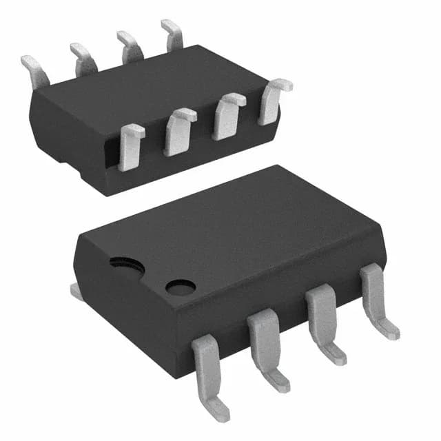
600 mA peak output — sizing the gate-drive budget
The Toshiba TLP351(TP1,F) is a single-channel optical-coupling gate driver delivering 600 mA peak output current, with 400 mA source and 400 mA sink capability. This output stage is sized for driving IGBTs and power MOSFETs in the 10 A to 30 A class where the total gate charge stays under roughly 100 nC — a common fit for motor-drive inverter legs, UPS power stages, and industrial SMPS. The 10 V to 30 V output supply range lets it run directly from a standard 15 V IGBT bias rail or a 12 V MOSFET rail, with enough headroom for desaturation protection circuits.
3750 Vrms isolation and 10 kV/µs CMTI — what they mean on the board
The 3750 Vrms isolation rating covers reinforced isolation for 240 VAC mains-connected equipment — the kind of safety barrier a motor-drive or grid-tied inverter needs between the low-voltage controller side and the high-voltage power stage. The 10 kV/µs common-mode transient immunity (CMTI) is the spec that keeps the gate drive from glitching when the switch node slews at tens of kV/µs during hard switching. A driver with marginal CMTI can latch the output high or low, blowing the power stage; this part's 10 kV/µs minimum is adequate for most 600 V IGBT bridges switching at moderate speed, though designs pushing 1200 V SiC or fast GaN edges may want a higher-rated part.
50 ns edges and 700 ns propagation delay — timing budget
Rise and fall times of 50 ns typical mean the driver can deliver the gate-charge pulse with edges fast enough to keep switching losses reasonable up to about 50 kHz. The 700 ns maximum propagation delay (both low-to-high and high-to-low) is the dead-time budget the PWM controller must account for — if the controller's own dead time is set to 500 ns, the total loop delay approaches 1.4 µs, which may limit minimum on-time in high-frequency designs. For sub-100 kHz IGBT switching this is not a constraint; for higher-frequency MOSFET stages the TLP352 family (200 ns propagation delay) is the faster alternative.
Package and temperature grade
The -40°C to 100°C operating temperature range covers industrial environments — motor drives in factory automation, outdoor telecom rectifiers, and engine-bay power stages that do not require the full 125°C automotive rating. The optical coupling technology provides galvanic isolation between input and output, eliminating ground-loop paths in noisy power-conversion applications.