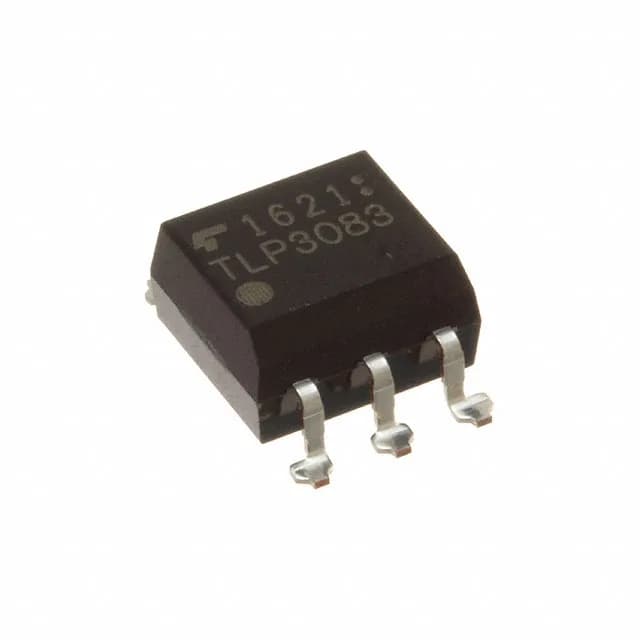
5000 Vrms isolation, 800 V off-state — what this phototriac does
The TLP3083F(D4,TP4F: The TLP3083F is a 1-channel phototriac from Toshiba, designed to switch AC loads with galvanic isolation. Its 5000 Vrms isolation rating makes it suitable for applications where the control side must be electrically separated from the load — think industrial motor drives, solid-state relays, or HVAC controllers where a microcontroller on the low-voltage side needs to switch 240 VAC or 480 VAC without a physical relay. The output triac can block 800 V off-state, which means it can handle the peak voltage of a 480 VAC line (about 678 V peak) with margin. The on-state current rating is 100 mA RMS — enough to drive a small relay coil, a contactor, or a triac gate directly, but not a high-current load. For larger loads, this part typically drives a power triac or a solid-state relay module. A built-in zero-crossing circuit turns on the triac only when the AC voltage crosses zero, which limits inrush current and reduces conducted EMI. This is a deliberate design choice: if your load is resistive (heater, incandescent lamp) or inductive (motor, solenoid), zero-crossing switching reduces stress on both the triac and the load.
2 kV/µs dV/dt — transient immunity in noisy environments
The minimum static dV/dt is 2 kV/µs, which is the rate of voltage rise across the triac that it can withstand without false triggering. In a factory floor with contactors, VFDs, or welding equipment, fast voltage transients on the AC line are common. A lower dV/dt rating would cause the triac to turn on unintentionally, potentially damaging the load or the triac itself. This rating gives confidence in industrial environments. The hold current (Ih) is 600 µA — the minimum current needed to keep the triac latched once triggered. Below this, the triac turns off at the next zero crossing. This is typical for phototriacs and means the load must draw at least 600 µA RMS to stay on; for very light loads (like an LED indicator), an external bleeder resistor may be needed.
Active lifecycle — no last-time-buy pressure
For BOM planning, this means you can commit the line without worrying about a sudden obsolescence-driven redesign. The part is offered in Tape & Reel (TR) and Cut Tape (CT) packaging, both in a 6-SMD gull-wing package with 5 leads. The supplier device package is 6-SMD. Surface-mount assembly with a 0.50 mm pitch — typical for this class of optoisolator. Approvals include CQC, CSA, cUL, UL, and VDE — these are the major safety agency certifications for reinforced insulation in power applications. If your end product needs to pass IEC 60950 or IEC 62368, having a VDE-approved optoisolator simplifies the certification process.
Zero-crossing vs non-zero-crossing — TLP3083F vs TLP3073
The closest functional sibling is the TLP3073, which shares the same 5000 Vrms isolation, 2 kV/µs dV/dt, and 6-SMD package. The key difference: TLP3073 does not have a zero-crossing circuit. If your load is purely resistive and you want to avoid the turn-on delay of zero-crossing (up to half a cycle), TLP3073 may be a better fit. But for inductive or capacitive loads, the zero-crossing feature of TLP3083F reduces inrush and EMI. Another sibling, the TLP3062A, also has zero-crossing and similar ratings but is listed with a different approval set (CQC, cUR, UR) and a slightly different package variant. The TLP3083F's VDE approval may be the deciding factor for European market designs.