Isolation and CTR — the two numbers that decide the fit
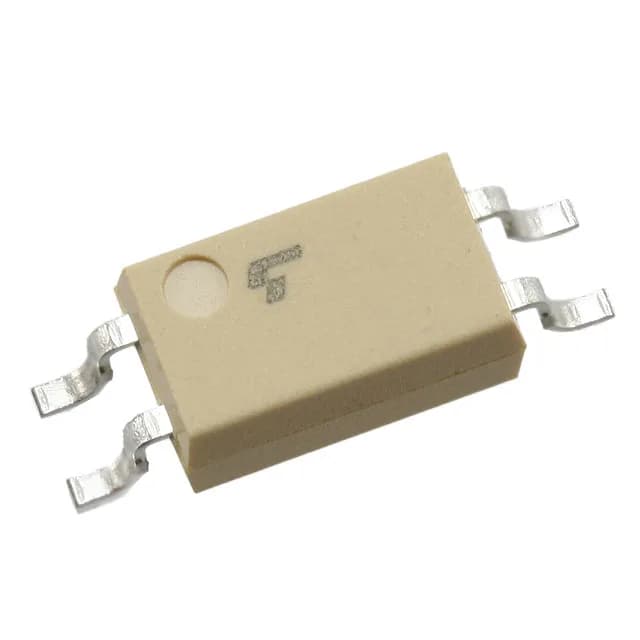
The TLP290(Y-TP,SE is a single-channel transistor-output optocoupler from Toshiba, rated for 3750Vrms isolation between input and output. That isolation voltage is the primary safety spec — it determines whether the part meets basic insulation requirements for mains-referenced circuits or reinforced insulation in a 250Vrms environment. The current transfer ratio (CTR) is specified as 50% minimum and 150% maximum at a forward current of 5mA. This range tells you the gain spread you must budget for: at the low end, the output transistor pulls only 2.5mA collector current for 5mA LED drive; at the high end, it pulls 7.5mA. If your downstream logic threshold needs a guaranteed collector current at a given LED current, you design around the 50% floor, not the typical.
AC/DC input — one part for both polarities
The input side accepts both AC and DC drive, which means the LED conducts on both half-cycles of an AC waveform. This is useful when the signal source is a bipolar AC line (e.g., zero-crossing detection from a mains transformer) or when you want to avoid a polarity-sensitive assembly step. The forward voltage is 1.25V typical, and the maximum continuous forward current is 50mA — derate for pulse operation if driving from a higher-voltage rail through a series resistor.
Switching speed and output ratings
Rise and fall times are 2µs and 3µs typical; turn-on and turn-off times are both 3µs typical. This puts the part in the general-purpose speed class — fine for 10 kHz to maybe 50 kHz switching, but not for high-speed digital isolation above 100 kHz. The output transistor is rated for 80V collector-emitter voltage and 50mA continuous current. Saturation voltage is 300mV maximum at the rated drive, which is low enough to interface with 3.3V or 5V logic without a pull-up resistor adjustment.
Temperature range and package
Operating temperature spans -55°C to 110°C, which covers industrial, automotive cabin, and some military/aerospace applications. The 4-SOIC package (4.55mm body width) is a compact surface-mount footprint. For 3750Vrms isolation in a 4-pin SOIC, the creepage distance is typically around 4mm — verify against your required clearance for the working voltage.
Lifecycle and sourcing
For dual-sourcing consideration, the TLP292(TPL,E is a functional peer with the same 3750Vrms isolation, transistor output, and AC/DC input, but its operating temperature extends to 125°C — a difference worth noting if your thermal budget pushes past 110°C.