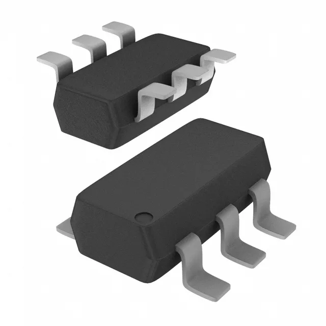
Toshiba Semiconductor RN1602(TE85L,F) — Interface & Transceivers

Toshiba RN1602(TE85L,F) Dual NPN Pre-Biased Transistor

MPNRN1602(TE85L,F)
End of Life

Toshiba RN1602(TE85L,F) dual NPN pre-biased digital transistor, 50 V Vce, 100 mA Ic, 250 MHz ft, 300 mW, SC-74 SOT-457 package, surface mount.

$0.37Ref. price · indicative, final on quote
PackagingSC-74, SOT-457
RoHSROHS3 Compliant
Sourced new & surplus through independent channelsAuthenticity-screened · ESD-safe packingListing updated Jul 2026

Specifications

RN1602(TE85L,F) specifications
ParameterValue
MountingSurface Mount
FET type2 NPN - Pre-Biased (Dual)
Voltage - collector emitter breakdown50V
Current - collector (Ic)100mA
Current - collector cutoff100nA (ICBO)
DC current gain (hFE) (Min) @ ic, vce50 @ 10mA, 5V
Power - max300mW
Frequency250MHz
PackageTape & Reel (TR); Cut Tape (CT)
CaseSC-74, SOT-457
Resistor - base (R1)10kOhms
Resistor - emitter base (R2)10kOhms
Vce saturation (Max) @ ib, ic300mV @ 250µA, 5mA

Product details

Dual NPN pre-biased — what it saves on the board

The Toshiba RN1602(TE85L,F) packs two NPN transistors with integrated 10 kΩ base and emitter-base resistors into a single SC-74 (SOT-457) package. That means one component replaces two discrete transistors plus four resistors — cuts placement cost and board area on high-count I/O banks, relay drivers, or LED matrix columns where each channel needs a simple switch. Each transistor handles up to 100 mA collector current and 50 V Vce breakdown, with a transition frequency of 250 MHz — fast enough for 1–2 MHz switching in solenoid or small-motor drive. The 300 mW total power ceiling (both transistors) means derating is real in a dense layout; keep the ambient under 85 °C if both channels run near 50 mA continuous.

300 mW — the derating number that matters

The 300 mW max power is the sum of both transistors in the SM6 package. At 100 mA Ic and 300 mV Vce(sat) the per-channel dissipation is 30 mW, so you've got headroom — but if one transistor saturates at higher current or the board runs hot, the junction temperature climbs fast. The SOT-457 footprint has no thermal pad; the heat goes through the leads. On a 2-layer board with minimal copper, 200 mW continuous per package is a safer design target.

Frequently asked questions

What is the closest functional equivalent to RN1602?

The RN1702,LF is a close parametric match — same dual NPN pre-biased topology, same 10 kΩ R1/R2, same 250 MHz ft and 300 mV Vce(sat) at 250 µA / 5 mA. The main difference is the RN1702 is rated at 200 mW max power versus the RN1602's 300 mW, so the RN1602 has more thermal headroom for higher duty-cycle switching.