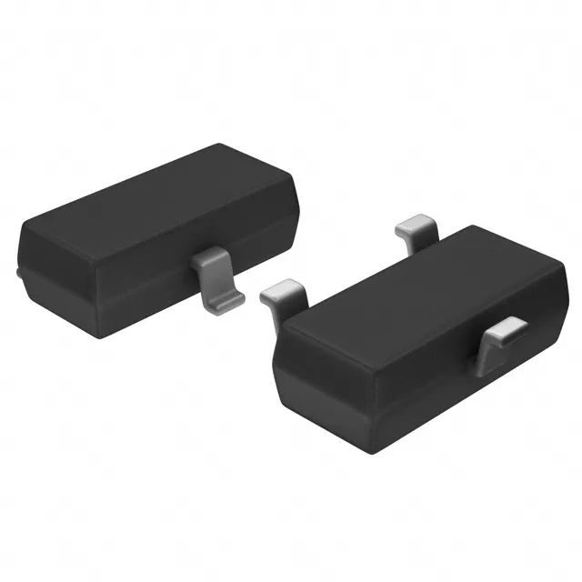
Toshiba Semiconductor RN1406,LF — Microcontrollers & Processors (MCU / MPU / DSP)

RN1406,LF NPN Pre-Biased Transistor, 50V 100mA, S-Mini

MPNRN1406,LF
End of Life

Toshiba RN1406,LF NPN pre-biased transistor, 50V Vce, 100mA Ic, 250MHz fT, internal R1=4.7 kOhms R2=47 kOhms, S-Mini (SC-59/SOT-23-3) package, surface mount, 200mW.

$0.21Ref. price · indicative, final on quote
PackagingTO-236-3, SC-59, SOT-23-3
RoHSROHS3 Compliant
Sourced new & surplus through independent channelsAuthenticity-screened · ESD-safe packingListing updated Jul 2026

Specifications

RN1406,LF specifications
ParameterValue
MountingSurface Mount
FET typeNPN - Pre-Biased
Voltage - collector emitter breakdown50 V
Current - collector (Ic)100 mA
Current - collector cutoff500nA
DC current gain (hFE) (Min) @ ic, vce80 @ 10mA, 5V
Power - max200 mW
Frequency250 MHz
PackageTape & Reel (TR); Cut Tape (CT)
CaseTO-236-3, SC-59, SOT-23-3
Resistor - base (R1)4.7 kOhms
Resistor - emitter base (R2)47 kOhms
Vce saturation (Max) @ ib, ic300mV @ 250µA, 5mA

Product details

Pre-biased NPN — the resistor divider is the part

The Toshiba RN1406,LF is an NPN pre-biased transistor in a S-Mini (SC-59 / SOT-23-3) surface-mount package. What makes it a 'digital transistor' is the monolithic bias network: a 4.7 kOhms base resistor (R1) and a 47 kOhms base-emitter resistor (R2) are integrated on the die. This eliminates two external passives from the BOM and shrinks the footprint to a single three-pin device.

50 V, 100 mA — where this sits in the switching lineup

Collector-emitter breakdown is rated at 50 V, continuous collector current at 100 mA, and saturation voltage is 300 mV at 250 µA base drive into 5 mA collector load. At 200 mW max power dissipation in the S-Mini package, derating is the main constraint above 85 °C ambient — the junction-to-ambient thermal path through the small SC-59 body limits continuous current in warm enclosures.

Frequently asked questions

What are the internal resistor values of RN1406?

The base resistor (R1) is 4.7 kOhms and the base-emitter resistor (R2) is 47 kOhms.

Is RN1406 equivalent to DTC114?

The DTC114 typically uses a 10 kOhm base resistor and 10 kOhm base-emitter resistor, giving a different input threshold and saturation characteristic. The RN1406's 4.7 kOhm / 47 kOhm divider produces a lower on-threshold and higher off-margin. They are not drop-in equivalents; check the resistor ratio against your base drive design.

Can RN1406 replace a standard NPN transistor like 2N3904?

Not directly. The RN1406 has integrated bias resistors that set a fixed base current for a given input voltage. A 2N3904 requires external base and base-emitter resistors to set the operating point. Replacing a 2N3904 with an RN1406 means removing those two resistors from the BOM, but the input impedance and drive requirements change — the circuit must be designed for the pre-biased topology, not swapped in as a one-for-one substitute.

When sourcing RN1406,LF, what's the closest functional second-source — RN1417(TE85L,F)?

The RN1417 is the same NPN pre-biased family with a different resistor ratio: R1=10 kOhms, R2=4.7 kOhms. It is a functional alternative if the base-drive threshold can be adjusted to suit the 10 kOhm input resistor. The package, voltage rating, current rating, and transition frequency are identical.