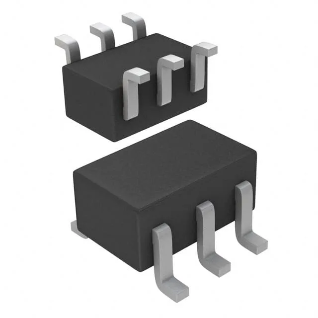
Toshiba Semiconductor HN1C01FU-Y,LXHF — Discrete Semiconductors

Toshiba HN1C01FU-Y,LXHF Dual NPN Transistor, 50V, 150mA

MPNHN1C01FU-Y,LXHF
End of Life

Toshiba Semiconductor HN1C01FU-Y,LXHF dual NPN transistor, 50 V collector-emitter breakdown, 150 mA collector current, 200 mW power dissipation, 80 MHz transition frequency, SOT-363 package, Tape & Reel.

$0.42Ref. price · indicative, final on quote
Packaging6-TSSOP, SC-88, SOT-363
Sourced new & surplus through independent channelsAuthenticity-screened · ESD-safe packingListing updated Aug 2026

Specifications

HN1C01FU-Y,LXHF specifications
ParameterValue
MountingSurface Mount
FET type2 NPN (Dual)
Voltage - collector emitter breakdown50V
Current - collector (Ic)150mA
Current - collector cutoff100nA (ICBO)
DC current gain (hFE) (Min) @ ic, vce120 @ 2mA, 6V
Power - max200mW
Frequency80MHz
PackageTape & Reel (TR); Cut Tape (CT)
Case6-TSSOP, SC-88, SOT-363
Vce saturation (Max) @ ib, ic250mV @ 10mA, 100mA

Product details

SOT-363 dual NPN — footprint and integration story

The HN1C01FU-Y,LXHF: The 0.65 mm lead pitch and 2.0 x 2.1 mm body footprint fit standard small-signal layouts; the two NPN die share a common collector pin, so the board trace for the collector bus must carry both channels' current. Rated for 150 mA collector current per transistor with a 50 V collector-emitter breakdown, this part handles low-to-mid current switching and amplification in automotive and industrial circuits. The 200 mW power dissipation ceiling means the total heat from both channels must stay under that limit — derate if ambient exceeds 25 °C. The 80 MHz transition frequency supports switching up to several MHz in pre-driver stages or signal conditioning; the minimum DC current gain of 120 at 2 mA, 6 V ensures consistent beta across the operating range for analog bias networks.

Automotive-grade parametrics and bias conditions

AEC-Q101 qualified per the description field, the HN1C01FU-Y,LXHF is screened for automotive reliability — the 100 nA maximum collector cutoff leakage at rated voltage holds up across temperature, critical for off-state power budgets in ECU modules. Vce saturation is 250 mV maximum at 10 mA base current and 100 mA collector current — this low saturation voltage keeps conduction losses minimal in saturated-switch applications like relay or LED drivers. The 150 mA collector current rating is the absolute maximum; continuous operation near this limit requires the board copper to sink the heat.

Package format and reel options

Surface mount only.

Frequently asked questions

What is the closest functional second-source for HN1C01FU-Y,LXHF?

The HN1C01FU-GR,LXHF is a direct peer — same dual NPN configuration, same 50 V breakdown, same 150 mA collector current, same 200 mW power dissipation, same 80 MHz transition frequency, and same SOT-363 package. The suffix difference (Y vs GR) typically indicates a hFE binning grade; the GR variant may have a different gain range. Check the specific hFE requirements of your circuit before substituting.

What compliance documentation does Toshiba Semiconductor provide for HN1C01FU-Y,LXHF?

The part carries AEC-Q101 automotive qualification. Standard Toshiba documentation includes RoHS and REACH compliance declarations.