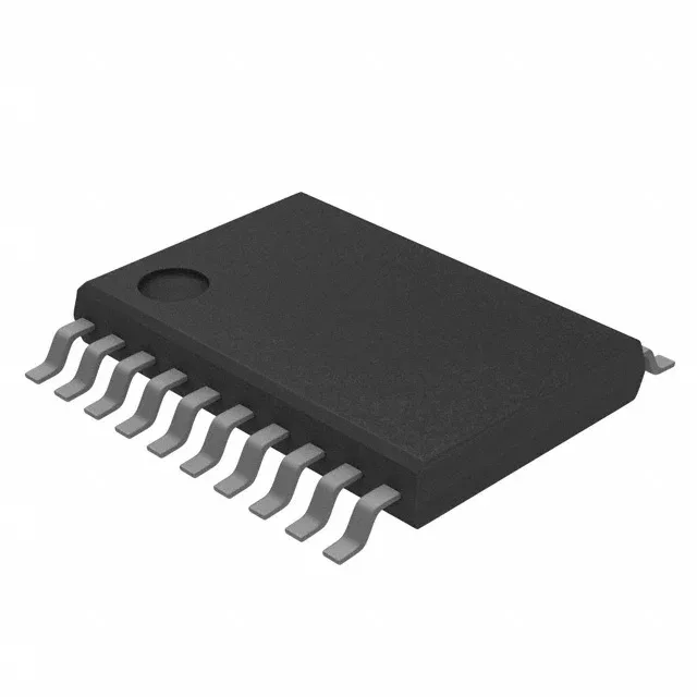
20-TSSOPB footprint and board integration
The 74VHC9273FT comes in a 20-TSSOP (4.40 mm width) package, supplier device package 20-TSSOPB, which is a standard 0.65 mm pitch footprint. The narrow body means the PCB land pattern must be precise — a 0.30 mm pad width on a 0.65 mm pitch leaves only 0.35 mm clearance between adjacent pads, so the solder mask registration needs to be tight to avoid bridging during reflow. MSL level isn't stated in the spec, but for a standard CMOS logic part in a TSSOP package, MSL 1 is typical — no bake required before reflow as long as the floor life isn't exceeded. The package is surface-mount only, so it's pick-and-place ready with no through-hole work.
100 MHz clock and 12.1 ns propagation delay — timing closure check
The 100 MHz clock frequency is the maximum toggle rate for the flip-flop itself, but the real timing budget for a design is set by the 12.1 ns max propagation delay at 5V with a 50 pF load. That delay includes the clock-to-Q time plus the output rise time into the load capacitance — so if the next stage has a setup time of 3 ns, the available clock period at 100 MHz (10 ns) is already tighter than the prop delay plus setup. At 100 MHz, you're running right at the edge; derate to 80 MHz or lower for reliable operation across temperature and process corners. The 4 pF input capacitance is typical for a 74VHC input stage — it won't load the clock driver significantly, but in a high-fanout design with eight flip-flops sharing the same clock line, the total load is 32 pF plus trace capacitance, which starts to matter for clock skew.
At 2V operation, the 100 MHz clock rate is not guaranteed; the max frequency drops with supply voltage, so for low-voltage battery applications, expect a lower toggle rate. The -40°C to 125°C operating temperature range is the full industrial grade — this part can sit in an engine bay or a rooftop solar inverter without derating. The quiescent current is only 4 µA, so in a battery-backed system that spends most of its time idle, the flip-flop's own draw is negligible.
Active lifecycle and compliance documentation
No minimum order quantity restrictions beyond the reel increment.