What the 1 MHz switching frequency means for your transformer design
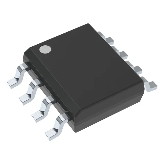
The UCC28C52DR is a current-mode PWM controller from TI that runs at 1 MHz switching — that's the number that sets your transformer core size and magnetics budget. At 1 MHz you can shrink the flyback or forward converter transformer compared to a 100 kHz design, but you need a core material rated for those frequencies (e.g., 3F3 or N87) and careful layout to keep switching losses in check. The part supports buck, boost, flyback, forward converter, and SEPIC topologies, so it's a single BOM line for multiple isolated and non-isolated rails. Supply voltage goes up to 30 V on Vcc, which means you can run it straight off a 24 V industrial bus without a series regulator. The 100% max duty cycle lets you operate in dropout or near-zero input-output differential in boost mode.
The 125°C TJ limit means you need to size the thermal path — 8-SOIC with no exposed pad relies on copper pour and airflow to keep the junction below that ceiling at full load.
Control features that simplify the loop
Built-in current limit, soft start, dead time control, enable, and frequency control reduce external component count. The synchronous rectifier output driver lets you use a MOSFET on the secondary side for better efficiency in low-voltage outputs.