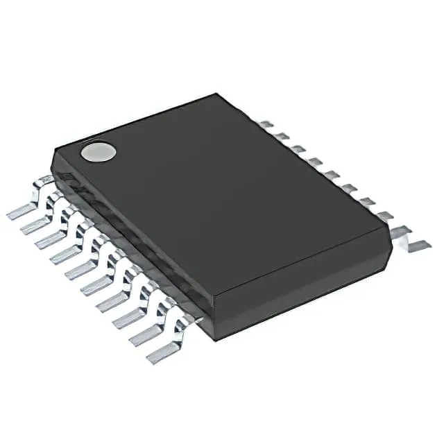
What this dual 16-bit counter does for your timing chain
It clocks on the positive edge of the input, incrementing two independent 16-bit counters up to a count rate of 25 MHz.
The 25 MHz count rate is the maximum input frequency at which the counter reliably increments on every positive edge. If your system clock or sensor pulse train runs at, say, 20 MHz, this part gives 5 MHz of headroom — enough to absorb jitter and propagation delay through the input buffer without missing counts. Below that rate the counter works fine, but the margin shrinks; at exactly 25 MHz you need clean edges and a layout that keeps the clock trace short and unterminated reflections low.
Two counters in one package — BOM consolidation
With two 16-bit binary counter elements in a single 20-TSSOP package, this IC replaces two discrete 16-bit counters, saving one component line and roughly 30% of the board area versus two SOIC-16 parts. Each element is independent, so you can use one for a frequency divider and the other for an event counter without cross-talk concerns — the internal logic isolates the two channels.
For programs that need multi-year supply assurance, this part does not carry the obsolescence risk that older 74-series logic variants often do.