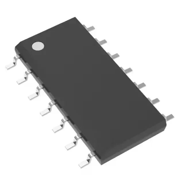
Texas Instruments SN74LS132D — DC-DC Power Modules

SN74LS132D 74LS Quad 2-Input NAND Gate, Schmitt Trigger

MPNSN74LS132D
End of Life

Texas Instruments 74LS series SN74LS132D, NAND Gate, Schmitt Trigger, 4 Circuit, 2 Input, 400µA, 8mA, 4.75V ~ 5.25V, 14-SOIC, 0°C ~ 70°C.

$0.99Ref. price · indicative, final on quote
Packaging14-SOIC (0.154", 3.90mm Width)
StockContact for availability
MOQ1 pcs
  • 100% new & originalTraceable channels only — no refurbs, no pulls, no remarked parts.
  • Date & lot codes on quoteStated per line before you commit; label photos on request.
  • MSL-compliant ESD packingMoisture-sealed bags with indicator cards; reels photo-verified.
  • PayPal buyer protectionPay by T/T, PayPal or Payoneer — card payments covered end to end.

Specifications

SN74LS132D Technical Specifications
ParameterValue
Series74LS
Logic typeNAND Gate
Mounting typeSurface Mount
Voltage4.75V ~ 5.25V
Current - quiescent11 mA
Current - output high, low400µA, 8mA
Number of inputs2
Operating temperature0°C ~ 70°C
PackageTube
FeaturesSchmitt Trigger
Case14-SOIC (0.154\", 3.90mm Width)
Number of circuits4
Input logic level - low0.5V
Input logic level - high1.9V
Max propagation delay @ v, max CL22ns @ 5V, 15pF

Product details

Quad 2-input NAND with Schmitt-trigger inputs — the noise-immune workhorse

The Texas Instruments SN74LS132D packs four independent 2-input NAND gates, each with Schmitt-trigger inputs, into a 14-SOIC package. The Schmitt-trigger action gives clean switching on slowly changing or noisy input signals — a common need in switch debounce, oscillator circuits, and line receivers where a plain 74LS00 would chatter. It runs on a 5V supply rail (4.75V to 5.25V) and is rated for the commercial temperature range of 0°C to 70°C, so it belongs in indoor, climate-controlled equipment like bench instruments, office peripherals, and telecom line cards.

22 ns propagation delay — timing margin in 5V logic

Max propagation delay is 22 ns at 5V with a 15 pF load. That is typical for the 74LS family — not a speed demon, but fast enough for most control and interface logic running at a few megahertz. The output drive is 400 µA sourcing and 8 mA sinking, enough to light a standard TTL input or a low-current LED, but do not expect to drive a long bus or a high-capacitance load without buffering.

Schmitt-trigger thresholds: 0.5V low, 1.9V high

The input logic levels are 0.5V max for a low and 1.9V min for a high, with hysteresis built into the Schmitt trigger. This means a slowly rising or falling signal — like a capacitor charging through a resistor in a simple RC oscillator — will still produce a clean, single-edged output. No extra debounce circuitry needed for mechanical switch inputs as long as the signal crosses those thresholds cleanly.

Active production, no end-of-life pressure

The SN74LS132D is listed as Active with ROHS3 compliance. The 14-SOIC package is a common footprint, so board layout is straightforward.

Frequently asked questions

Is SN74LS132D equivalent to 74LS132?

Yes. SN74LS132D is the specific Texas Instruments order code for a 74LS132 quad 2-input NAND gate with Schmitt-trigger inputs in a 14-SOIC surface-mount package. The 'SN' prefix is TI's commercial prefix; the core function and logic family are identical to the generic 74LS132.

What is the difference between 74LS132 and 74HC132?

The 74LS132 runs on a 5V supply and uses bipolar LS technology with a quiescent current of 11 mA. The 74HC132 is a CMOS part that runs on a wider supply range (2V to 6V) and draws far less quiescent current — typically microamps. The HC version also has faster propagation delay at 5V. If you are on a tight power budget or need a wider supply range, the 74HC132 is the better fit; for a drop-in replacement in an existing 5V LS design, the 74LS132 works as-is.

Can I use SN74LS132N instead of SN74LS132D?

The SN74LS132N is the same die in a DIP-14 through-hole package, while the SN74LS132D is in a 14-SOIC surface-mount package. Electrically they are identical — same Schmitt-trigger NAND gates, same 5V supply, same timing. The swap is purely a board-level footprint decision: the DIP version needs a through-hole PCB, the SOIC version needs a surface-mount pad layout. They are not pin-compatible on the same board without an adapter.