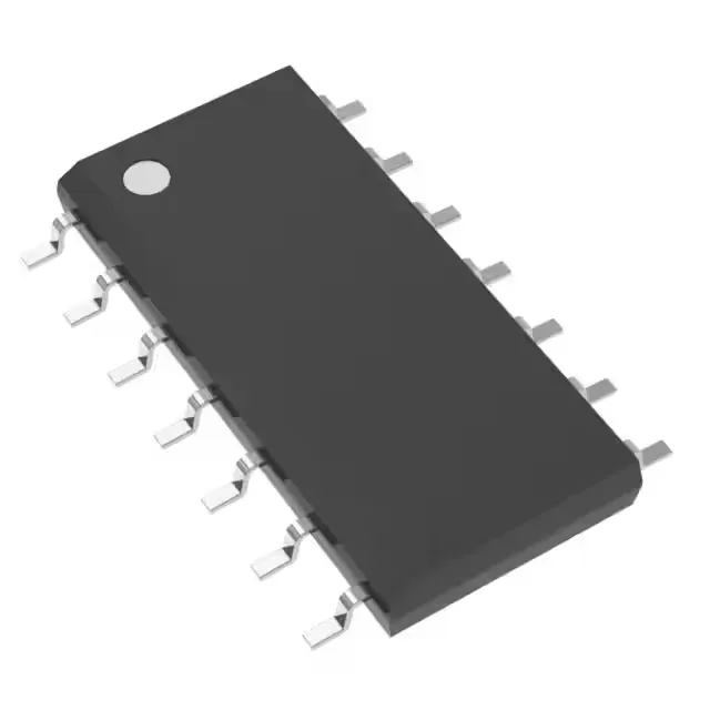
Texas Instruments SN74HCT14D — DC-DC Power Modules

SN74HCT14D 74HCT Hex Inverter with Schmitt Trigger, 30 ns

MPNSN74HCT14D
End of Life

Texas Instruments 74HCT series, Logic type Inverter, Schmitt Trigger, 6 Circuits, 1 Input, 4mA output, 4.5V to 5.5V supply, -40°C to 85°C, Surface Mount 14-SOIC.

$1.16Ref. price · indicative, final on quote
Packaging14-SOIC (0.154", 3.90mm Width)
StockContact for availability
MOQ1 pcs
  • 100% new & originalTraceable channels only — no refurbs, no pulls, no remarked parts.
  • Date & lot codes on quoteStated per line before you commit; label photos on request.
  • MSL-compliant ESD packingMoisture-sealed bags with indicator cards; reels photo-verified.
  • PayPal buyer protectionPay by T/T, PayPal or Payoneer — card payments covered end to end.

Specifications

SN74HCT14D Technical Specifications
ParameterValue
Series74HCT
Logic typeInverter
Mounting typeSurface Mount
Voltage4.5V ~ 5.5V
Current - quiescent2 µA
Current - output high, low4mA, 4mA
Number of inputs1
Operating temperature-40°C ~ 85°C
PackageTube
FeaturesSchmitt Trigger
Case14-SOIC (0.154\", 3.90mm Width)
Number of circuits6
Input logic level - low0.5V ~ 0.6V
Input logic level - high1.9V ~ 2.1V
Max propagation delay @ v, max CL30ns @ 5.5V, 50pF

Product details

Six Schmitt-trigger inverters in a 14-SOIC — what it does and where it fits

The Texas Instruments SN74HCT14D packs six independent inverter gates with Schmitt-trigger inputs into a 14-SOIC surface-mount package. Each channel takes one input and delivers a clean inverted output, with the Schmitt action providing hysteresis that cleans up slow edges, noisy signals, or switch-contact bounce. It runs from a 4.5 V to 5.5 V supply and draws just 2 µA quiescent, making it a natural fit for 5 V industrial control, PLC I/O modules, sensor conditioning, and any board where a noisy backplane needs signal cleanup before it hits the MCU. The -40°C to 85°C range covers factory-floor and outdoor telecom cabinets without qualification surprises.

30 ns propagation delay — timing budget for a 5 V bus

The 30 ns max propagation delay at 5.5 V and 50 pF load sets the timing margin for control and data signals running across a backplane or between logic families. At 5 V nominal the delay is typically shorter, but the 30 ns ceiling is the number to use in worst-case timing analysis. For a 10 MHz clock path that leaves about 70 ns of the period for setup and hold — plenty for most 5 V logic, but worth checking if the signal passes through multiple gates in series. The 4 mA output drive at both high and low levels is enough to drive a handful of CMOS loads or a short ribbon cable, but not a long bus without a buffer.

Schmitt trigger — what it cleans up

The Schmitt-trigger inputs define two distinct thresholds: a low-going input below 0.5 V to 0.6 V reads as a logic 0, and a high-going input above 1.9 V to 2.1 V reads as a logic 1. The gap between them — roughly 1.3 V of hysteresis — rejects noise and prevents multiple transitions on a slowly rising signal from a capacitor, a sensor, or a mechanical switch. That hysteresis is what makes this part the go-to for debouncing pushbuttons, squaring up a 50/60 Hz line-frequency signal, or cleaning the output of an optocoupler that has a slow turn-on edge.

SOIC-14 — rework and footprint notes

The 14-SOIC body measures 3.90 mm wide with 0.154" pitch — a standard footprint that reflows cleanly with a typical leaded profile. The 2 µA quiescent current means no thermal concern even in still air, so no thermal pad or via stitching is needed.

Lifecycle and supply posture

The SN74HCT14D carries an Active lifecycle status with ROHS3 compliance. For dual-sourcing or a lower-power alternative, the SN74HCS04PWR (2 V to 6 V, 16 ns at 6 V, 125°C rated) is a functional peer in the same 6-channel inverter family — but the HCT14D runs from 5 V only and uses the original HCT thresholds, so verify the logic levels before swapping.

Frequently asked questions

What is the difference between SN74HCT14D and SN74HC14D?

The SN74HCT14D is the HCT (High-Speed CMOS, TTL-compatible) version, with input thresholds set to 0.8 V and 2.0 V typical to interface directly with TTL logic. The HC version uses CMOS thresholds at 0.3 V and 1.7 V typical. For a 5 V system with mixed TTL and CMOS, the HCT variant avoids level-shifting. Both are hex Schmitt-trigger inverters in the same pinout and package.

Is the SN74HCT14D a Schmitt trigger device?

Yes, each of the six inverter channels has a Schmitt-trigger input with hysteresis for noise rejection and slow-edge cleanup.