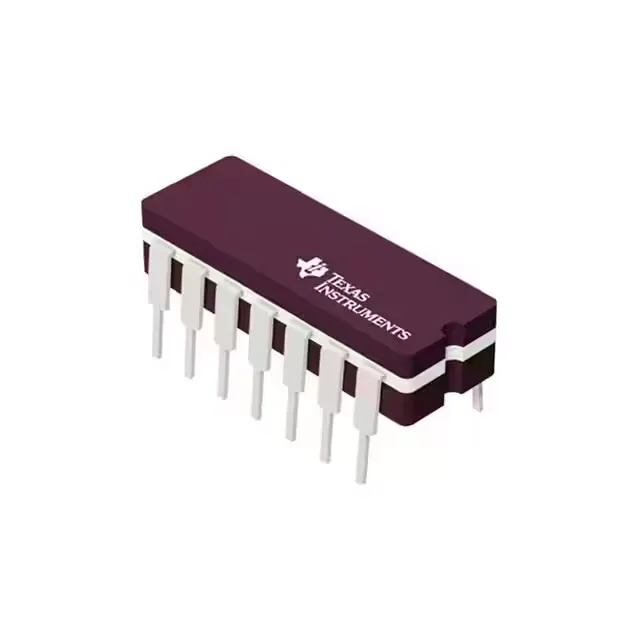
Quad 2-input NAND in the 74F family — what the 5 ns propagation delay buys you
The SN74F00N is a Texas Instruments 74F-series quad 2-input NAND gate in a through-hole 14-DIP package. It operates from a 4.5 V to 5.5 V supply and is specified for the commercial temperature range of 0°C to 70°C. The headline rating is the 5 ns maximum propagation delay at 5 V with a 50 pF load — that is the timing budget you design to for high-speed glue logic, address decoding, or clock gating in 5 V systems. The asymmetric output drive (1 mA source, 20 mA sink) is typical of bipolar TTL and limits direct LED drive to the sink side unless you buffer.
5 V logic compatibility and input thresholds
Input logic-low threshold is 0.8 V; logic-high is 2 V. That means the SN74F00N accepts standard 5 V TTL and 3.3 V CMOS levels that swing above 2 V — no level translation needed when driving from a 3.3 V output that meets V_IH(min). The 4.5 V to 5.5 V supply range also covers the nominal 5 V rail with margin for ripple and regulation tolerance.
Package and footprint — through-hole DIP for prototyping and legacy boards
Housed in a 14-DIP (0.300", 7.62 mm) body with a 14-PDIP supplier package designation. The through-hole mounting suits breadboard prototyping, socketed designs, or rework on existing boards where a SOIC or TSSOP would require a layout change. The 0.300" row spacing is the standard narrow DIP footprint.
No last-time-buy or phase-out notice is in effect, so the part is safe to specify for new production builds.