Energy-measurement MCU with integrated sigma-delta ADC
The distinguishing feature is the pair of 16-bit sigma-delta ADCs (A/D 2x16b), purpose-built for energy-measurement front ends. An integrated LCD driver, brown-out detect/reset, POR, PWM, and watchdog timer round out the peripheral set, reducing external BOM for a standalone meter or sensor node.
At 8 MHz the CPU16 core executes most instructions in one or two cycles, giving a throughput of roughly 4 to 8 MIPS. That is enough for the real-time math inside a single-phase energy meter — voltage and current sample pairs at a few kHz, multiply-accumulate for active power, and periodic LCD refresh. It is not a part you would pick for high-speed control or heavy protocol stacks; the SPI and UART/USART interfaces run comfortably at this clock, but the bus margin is tight if you try to push the serial ports near their maximum bit rate while the ADC is converting.
The base product number MSP430FE4232 covers the whole family variant; the IPMR suffix identifies the 64-LQFP package on tape-and-reel. If you are qualifying a meter design today, the active status gives a multi-year sourcing window, though as with any mature 16-bit line, it is worth checking the PCN history on the TI portal before a high-volume commit.
Dual 16-bit sigma-delta ADC — the reason this part exists
The two 16-bit sigma-delta ADCs are the headline feature that separates the FE4232 from a generic MSP430. They are designed for simultaneous sampling of voltage and current channels in an energy-measurement application — the typical use case is a shunt- or CT-based meter where one ADC digitises the line voltage and the other digitises the load current. The 16-bit resolution gives enough dynamic range to measure from a few milliamps to the rated full-scale current without an external PGA, provided the input signal is scaled to the ADC's full-scale range. The sigma-delta architecture also provides inherent noise shaping that pushes quantisation noise out of the power-line frequency band, which simplifies the digital filtering needed for active-power computation. For a BOM engineer, this means the external analog front end can be as simple as a resistor divider and a shunt — no separate ADC, no reference IC, no anti-aliasing filter beyond a first-order RC.
Package and footprint — 64-LQFP with LCD drive
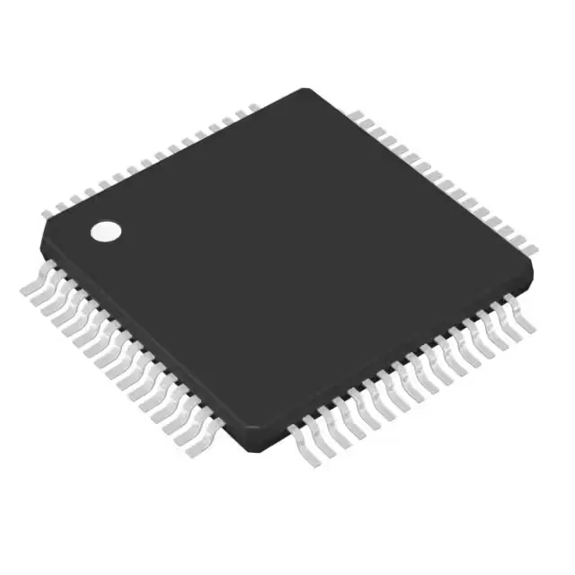
The 64-LQFP package (10x10 mm body,) provides 14 general-purpose I/O pins plus dedicated LCD segment and common outputs. The LCD driver can drive up to 4-mux or 8-mux passive LCD glass directly, which is typical for a 6+2 digit meter display. The 14 I/O count is modest — most of the 64 pins are consumed by the LCD drive, the dual ADC inputs, and the SPI/UART serial interfaces. For layout, the 0.5 mm pitch LQFP is straightforward for a two-layer board, but the LCD segment traces should be kept short and away from the ADC input traces to avoid coupling noise into the measurement channel.