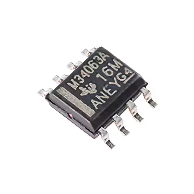
What the 1.5 A switch rating means for your rail
The MC34063ADR integrates a 1.5 A switch transistor — that is the peak current the internal pass device can handle, not the continuous output current. In a typical buck converter from 12 V to 5 V, you can expect about 750 mA continuous output before the switch current limit is hit; for a boost from 5 V to 12 V, the available output current drops to roughly 400 mA because the switch handles the input current, which is higher than the output. If your load exceeds that, you need an external pass transistor or a higher-current regulator like the LMS3655MQURNLRQ1.
100 kHz switching — forgiving layout, larger passives
The 100 kHz switching frequency is a deliberate choice: it keeps switching losses low and makes the PCB layout forgiving — you can route the power path without worrying about MHz-range ringing. The trade-off is that the inductor and output capacitor values are larger than what a 400 kHz or 2.1 MHz part would need. For a 5 V / 500 mA buck, expect a 100–220 µH inductor and 100–470 µF output cap; compare that to the LMR33630APCQRNXRQ1 at 2.1 MHz, which would use a 4.7 µH inductor and 22 µF ceramic.
If your board goes into a motor drive, outdoor telecom cabinet, or automotive bay, you need the industrial or automotive grade sibling — the LMS3655MQURNLRQ1, for example, is rated -40°C to 150°C and is AEC-Q100 qualified.
Buck, boost, or invert — one part for multiple rails
The MC34063ADR can be configured as a step-down (buck), step-up (boost), or voltage-inverting regulator. The output is adjustable from 1.25 V up to 40 V.