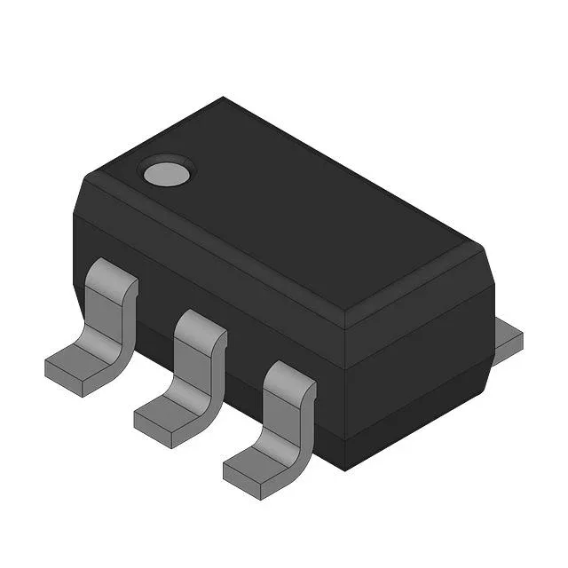
1.7 GHz current-feedback amp — what the bandwidth and slew rate mean for your signal chain
That bandwidth stays nearly flat across gain settings because the current-feedback topology decouples gain from bandwidth — unlike a voltage-feedback amp where increasing gain directly cuts the usable frequency range. The single-circuit (one amplifier per SOT-23-5 package) keeps parasitic capacitance low and layout compact, but for multi-channel systems you will need one package per channel.
The supply voltage span is 10 V minimum to 12 V maximum — a narrow, relatively high window. This part will not run from a 5 V or 3.3 V rail; it needs a regulated 10–12 V supply, typically implemented as a ±5 V split supply or a single 12 V rail with a virtual ground. The 12.5 mA quiescent supply current per amplifier is modest for this speed class, but the 80 mA output current per channel gives you headroom to drive 50 Ω back-terminated cables or the sampling capacitor of a 12-bit, 250 MSPS ADC. The 1 mV input offset voltage and 6 µA input bias current are typical for a current-feedback design at this speed — expect offset drift to be a few µV/°C, so a DC servo or AC coupling is advisable if the downstream stage cannot tolerate a few millivolts of DC shift over temperature.
For supply-chain resilience, the THS4215DRBT is a voltage-feedback alternative in the same speed class (350 MHz bandwidth, 970 V/µs slew rate) but note the different topology — the THS4215 trades some bandwidth flatness for lower input bias current and a wider supply range, so a direct drop-in substitution requires checking the compensation and feedback network.