3V to 65V automotive ORing controller with fast failover
The Texas Instruments LM74801QDRRRQ1 is an automotive-grade N+1 ORing controller designed for redundant power supply architectures. It operates from a 3V to 65V supply rail, making it suitable for 12V, 24V, and 48V automotive systems where a single supply failure must not interrupt the load. The controller drives an external N-channel MOSFET and provides a 1:1 input-to-output ratio, acting as an ideal diode replacement with controlled turn-on and fast reverse-current blocking.
Turn-on and turn-off timing — what the delays mean for failover
A 2.6 µs turn-on delay and 500 ns turn-off delay define the transition window during a supply rail switchover. The 500 ns turn-off response is the critical parameter: when the primary supply drops, the controller must open the external FET fast enough to prevent reverse current from the backup rail back-feeding into the failed supply. In a dual-battery or redundant PSU setup, this sub-microsecond reaction time keeps the load rail stable without droop that could reset an ECU or microcontroller.
AEC-Q100 qualification and automotive deployment
The ROHS3 compliance and wettable flank package option support automated optical inspection in high-volume automotive assembly lines.
Package and footprint — 12-WSON with exposed pad
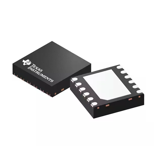
The part is offered in a 12-WFDFN exposed pad package, also specified as a 12-WSON with 3x3 mm body dimensions. The wettable flank plating aids solder joint inspection after reflow.
External N-channel MOSFET — BOM selection note
The LM74801QDRRRQ1 does not integrate the power switch internally. An external N-channel MOSFET must be selected based on the system's maximum load current (rated up to 5A output from the controller) and the supply voltage range. The FET's gate is driven by the controller's charge pump; choose a device with a gate threshold voltage (Vgs(th)) low enough to be fully enhanced at the minimum operating supply voltage of 3V. The controller handles the ORing logic and gate drive, while the FET handles the conduction and reverse-blocking.