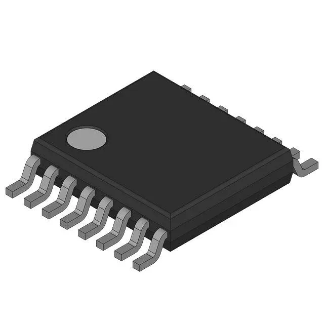
Texas Instruments LM5026MT — Analog & Data Acquisition

LM5026MT Switching Controller, Current-Mode

MPNLM5026MT
End of Life

Texas Instruments LM5026MT, current-mode PWM switching controller, Step-Up/Step-Down function, Forward Converter topology, 200kHz-590kHz switching, 70%-80% max duty cycle, 2 outputs, 16-TSSOP package, -40°C to 125°C junction temp.

$2.74Ref. price · indicative, final on quote
Packaging16-TSSOP (0.173", 4.40mm Width)
RoHSRoHS non-compliant
Independent supplier — new & surplus stockAuthenticity-screened · ESD-safe packingListing updated Aug 2026

Specifications

LM5026MT specifications
ParameterValue
Output typeTransistor Driver
MountingSurface Mount
Voltage - supply (Vcc (Vdd))8V ~ 15V
Frequency - switching200kHz ~ 590kHz
I/O channels2
Output phases1
Duty cycle70%, 80%
Operating temperature-40°C ~ 125°C (TJ)
PackageBulk
FunctionStep-Up/Step-Down
TopologyForward Converter
Clock syncYes
Case16-TSSOP (0.173\", 4.40mm Width)
Control featuresDead Time Control, Frequency Control, Reset, Soft Start
Output configurationPositive, Isolation Capable
Synchronous rectifierNo

Product details

Current-mode forward converter controller for isolated and non-isolated designs

The Texas Instruments LM5026MT is a current-mode PWM controller built for forward converter topologies, supporting both step-up and step-down output configurations. It drives two external transistors with a switching frequency adjustable from 200 kHz to 590 kHz, giving the designer room to optimize magnetics size against switching losses. The controller includes dead time control, frequency control, reset, and soft start — features that help shape the power stage response and manage inrush on startup.

Maximum duty cycle is 70% and 80%.

The controller runs from an 8 V to 15 V supply rail — typical for a bias supply derived from the main DC bus or an auxiliary winding. The two outputs drive external transistors directly; the output configuration is positive and isolation-capable, meaning an optocoupler or pulse transformer can close the feedback loop across the isolation barrier. There is no synchronous rectifier driver on-chip, so the secondary-side rectification uses Schottky or ultrafast diodes, which keeps the BOM simple for lower-output-current designs.

It is listed as RoHS non-compliant, which matters for designs that must meet EU RoHS directives — verify your exemption or alternate compliance path if your BOM requires full RoHS conformance.

Frequently asked questions

What are alternatives to LM5026MT?

The LM5150QURUMRQ1 is a functional alternative if you need an automotive-grade (AEC-Q100) boost controller with a higher switching frequency up to 2.3 MHz and a single output. The UCC2806DWTR is another option for step-up/step-down forward converters with synchronous rectifier support, but it has a lower maximum duty cycle of 50% and a narrower temperature range of -40°C to 85°C. Neither is a pin-compatible drop-in — evaluate the control feature set and supply voltage range against your design.

What is the maximum duty cycle of LM5026MT?

The LM5026MT has a maximum duty cycle listed at 70% and 80%, depending on the output configuration or operating mode. This allows higher step-down ratios in forward converter designs without requiring a separate reset winding.

Is LM5026MT RoHS compliant?

No, the LM5026MT is listed as RoHS non-compliant. Check your assembly house's exemption policy or confirm whether an RoHS-compliant variant exists for your production region.