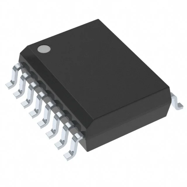
What this automotive isolator brings to the BOM
It pushes 25 Mbps per channel across a 4000 Vpk isolation barrier, with a 3/1 input-to-output split — three channels on the input side, one on the output side. That 3/1 ratio fits a common pattern: isolate three sensor or control signals into a single MCU receive line, or three PWM commands out with one feedback channel back.
At 25 Mbps the part handles SPI clock rates up to 12.5 MHz (half-duplex) or full-duplex SPI at 25 Mbps, plus CAN FD at 5 Mbps with margin, and UART up to 3.125 Mbps. Propagation delay maxes at 45 ns each way, which is tight enough that a 25 Mbps SPI transaction finishes within one 40 ns clock period — no need to stretch the clock for isolation latency. Pulse-width distortion stays under 5 ns, so duty-cycle-sensitive signals like PWM or Manchester-encoded data don't accumulate timing error across the barrier.
125 °C and 25 kV/µs CMTI — built for the engine bay
The common-mode transient immunity of 25 kV/µs minimum means it won't glitch when a nearby solenoid or IGBT switching event slams a fast voltage step across the barrier — a real failure mode in motor-drive and inverter environments. Rise and fall times are a tight 2 ns typical, keeping the output edges clean for the downstream logic without excessive ringing.
Surface-mount only, so plan for reflow assembly. No isolated power on-chip; the output side needs its own supply rail (same 3.15 V to 5.5 V range). The 16-SOIC footprint is shared across the ISO7241 family, so swapping between speed or channel-config variants is a direct BOM drop-in.
That means no last-time-buy clock ticking — you can commit this part to a production BOM without building an obsolescence contingency.