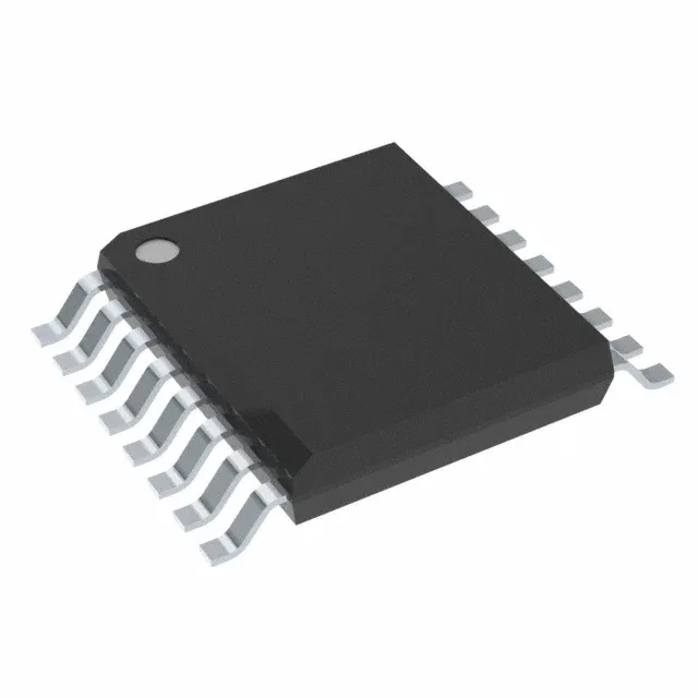
Quad-channel capacitive isolator for automotive and industrial isolation barriers
The ISO7041QDBQRQ1: It provides 3000Vrms galvanic isolation across a 3V to 5.5V supply range, with a data rate of 4 Mbps and a typical rise/fall time of 16 ns. The channel configuration is three inputs on side 1 and one input on side 2, making it suitable for isolating SPI, UART, or general-purpose digital signals where the majority of traffic flows in one direction.
50 kV/µs CMTI — what it means for motor-drive and inverter designs
The common-mode transient immunity of 50 kV/µs (minimum) is the key parameter for maintaining data integrity in environments with fast-switching power stages, such as traction inverters, DC-DC converters, and motor drives. A CMTI rating this high ensures that the output does not glitch when a high dv/dt transient couples across the isolation barrier — a common failure mode in SiC and GaN-based designs where switching edges exceed 50 V/ns. For a 3/1 channel part, the single reverse-direction channel is typically used for fault or status feedback, while the three forward channels carry PWM or data.
Propagation delay and pulse-width distortion
Maximum propagation delay of 165 ns (both directions) and pulse-width distortion of 10 ns define the timing budget for closed-loop control loops. At 4 Mbps, the bit period is 250 ns, so the 165 ns delay consumes about 66% of the period — adequate for most SPI and UART isolation applications, but the designer should verify setup/hold margins at the receiver. The 10 ns pulse-width distortion means the high and low pulses at the output differ by no more than 10 ns, which is tight enough for PWM duty-cycle accuracy in motor control.
Active lifecycle and AEC-Q100 qualification
It is fully ROHS3 compliant. The AEC-Q100 qualification (grade 1, implied by the 125°C operating temperature) covers the device for automotive under-hood and chassis-domain applications, as well as industrial environments requiring extended temperature range and reliability screening.
Supply voltage and 5V system compatibility
For a 5V system, the part operates at the upper end of the range, providing full 5V CMOS logic levels on both sides of the isolation barrier. The capacitive coupling technology does not require a separate isolated power supply for the data channels — the isolated power flag in the spec indicates the part includes an integrated DC-DC converter or supports an external isolated supply for the secondary side; in this device, the secondary-side logic power is derived from the primary-side supply through the isolation barrier, simplifying board layout.