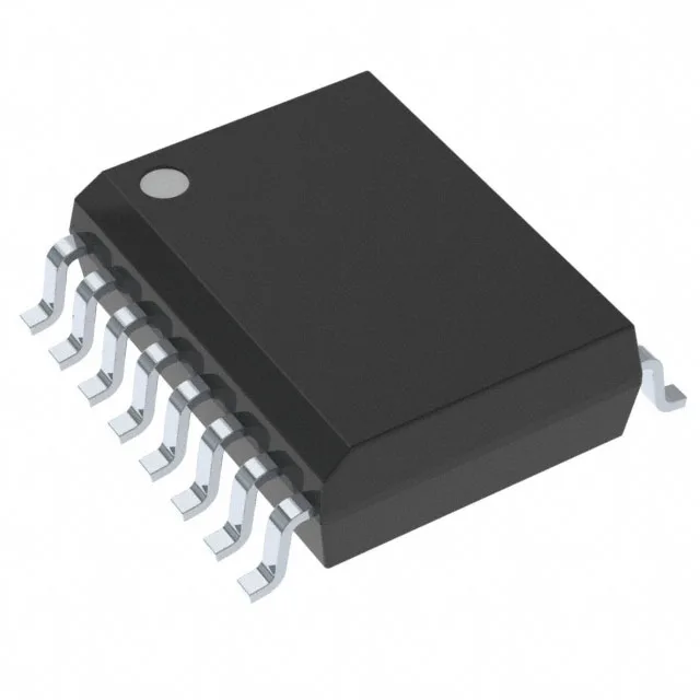
Six-channel SPI isolator built for the automotive bus
The Texas Instruments ISO6763FQDWRQ1 is a 6-channel, unidirectional SPI digital isolator using capacitive coupling, rated for 50 Mbps data rate and 5000 Vrms isolation. It belongs to the ISO676x-Q1 series qualified to AEC-Q100, making it a fit for automotive powertrain, battery management, and motor-drive systems where galvanic isolation between the controller and high-voltage domain is mandatory. Three channels run each direction — Side 1 gets three inputs, Side 2 gets three — which maps neatly to a standard SPI bus (SCK, MOSI, CS) plus a few GPIO or interrupt lines.
100 kV/µs CMTI — the number that matters in an inverter
That is the spec that keeps the data path from glitching when a SiC or IGBT switch transitions at several thousand volts per microsecond on the other side of the isolation barrier. In a traction inverter or an on-board charger, a weaker CMTI number means bit errors on the SPI bus during switching events — this part is specced to avoid that.
Propagation delay and pulse-width distortion — timing budget for the SPI clock
Maximum propagation delay is 18 ns in both directions, with pulse-width distortion capped at 7 ns. Rise and fall times are 4.5 ns typical. For a 50 Mbps SPI bus running at 25 MHz clock, that 18 ns eats into the setup-and-hold window on the far side — budget it when you close timing, especially across temperature. The 7 ns PWD means the high and low pulses stay reasonably symmetric, which helps keep the duty cycle distortion under control.
No isolated power is built in — you supply the secondary-side rail separately, which is the usual approach for SPI isolators where the bus master and slave each have their own local regulator.
Package and temperature — wide-body SOIC for creepage, 125°C for under-hood
It is ROHS3 compliant.