What the 5 µV offset and 14 kHz bandwidth mean for your measurement chain
Its 5 µV input offset voltage sets the floor for the smallest current you can resolve across a shunt — at a 10 mΩ sense resistor, that offset corresponds to 500 µA of apparent current error before any gain-stage noise. The 14 kHz gain-bandwidth product tells you this part is designed for DC and low-frequency measurements: motor-winding current, battery charge/discharge, power-supply load monitoring. It is not a fit for switching-regulator inductor current sensing where you need MHz bandwidth. The supply voltage span runs from 2.7 V to 26 V, so the same BOM line works on a 3.3 V logic rail, a 5 V automotive bus, or a 24 V industrial supply. Quiescent current is 65 µA, low enough to leave the amplifier powered continuously in a battery-monitoring application without a dedicated load-switch.
The Zero-Drift architecture keeps the offset drift low across this span — the 5 µV figure is the max at 25°C, and the auto-zero loop holds it tight over temperature.
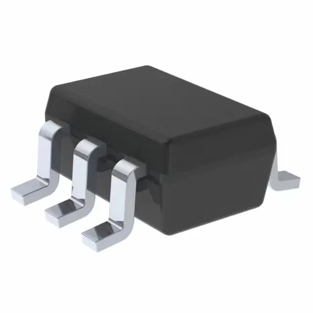
The SC-70-6 footprint is 2.1 mm × 2.0 mm — roughly half the area of an SOIC-8. That saves board space in multi-channel designs, but the small pad means the reflow profile needs a good paste deposit on the centre pad if the part has one (this package does not have an exposed thermal pad; dissipation is through the leads). Surface-mount only.