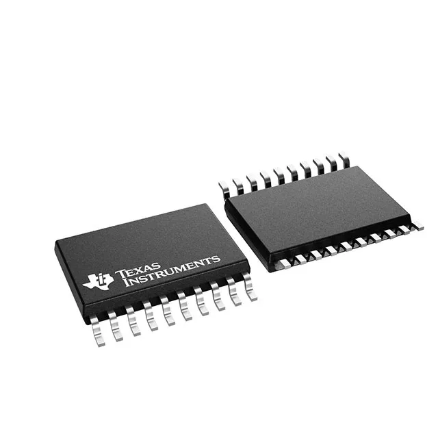
Texas Instruments DRV8300UDIPWR — Logic ICs

DRV8300UDIPWR 100-V half-bridge gate driver, 1.5 A sink

MPNDRV8300UDIPWR
End of Life

Texas Instruments DRV8300UDIPWR, three-phase half-bridge gate driver, N-Channel MOSFET, 8.7V to 20V supply, 125 V bootstrap, 1.5 A peak sink, 24 ns rise, 20-TSSOP, -40°C to 125°C.

$1.75Ref. price · indicative, final on quote
Packaging20-TSSOP (0.173", 4.40mm Width)
StockContact for availability
MOQ1 pcs
  • 100% new & originalTraceable channels only — no refurbs, no pulls, no remarked parts.
  • Date & lot codes on quoteStated per line before you commit; label photos on request.
  • MSL-compliant ESD packingMoisture-sealed bags with indicator cards; reels photo-verified.
  • PayPal buyer protectionPay by T/T, PayPal or Payoneer — card payments covered end to end.

Specifications

DRV8300UDIPWR Technical Specifications
ParameterValue
Gate typeN-Channel MOSFET
Input typeNon-Inverting
Channel typeIndependent
Mounting typeSurface Mount
Voltage8.7V ~ 20V
Logic voltage - VIL, VIH0.8V, 2V
High side voltage - max (Bootstrap)125 V
Current - peak output (Source, sink)750mA, 1.5A
Operating temperature-40°C ~ 125°C (TA)
PackageTape & Reel (TR); Cut Tape (CT)
Case20-TSSOP (0.173\", 4.40mm Width)
Number of drivers2
Driven configurationHalf-Bridge
Rise (Fall time)24ns, 12ns

Product details

Three-phase half-bridge driver for 12 V to 100 V motor rails

The Texas Instruments DRV8300UDIPWR is a three-phase half-bridge gate driver designed for N-channel MOSFETs in motor-drive and power-conversion stages. It drives two independent half-bridge channels with a peak source current of 750 mA and a peak sink current of 1.5 A, enough to charge and discharge the gate capacitance of medium-power MOSFETs in the 20 A to 40 A output range. The bootstrap high-side voltage is rated to 125 V, so the part handles 48 V and 72 V DC bus rails with margin, and the 8.7 V to 20 V supply range covers standard 12 V and 24 V industrial supplies. Typical rise and fall times are 24 ns and 12 ns respectively, which keeps cross-conduction losses manageable when the dead time is set correctly.

1.5 A peak sink — sizing the gate drive for your MOSFET

The 1.5 A peak sink current is the number to check against your MOSFET's total gate charge. A MOSFET with a 50 nC Qg at the chosen drive voltage will switch in roughly 33 ns with this driver, assuming a 1 Ω gate resistor and minimal PCB inductance. The 750 mA source peak is lower, so the turn-on edge is softer than turn-off — a natural asymmetry that helps control di/dt during turn-on without adding an external Schottky in parallel with the gate resistor. No level-shifting is needed when the MCU supply matches the driver's logic supply.

Package, footprint, and sourcing posture

The mounting is surface-mount, and the supplier device package is 20-TSSOP.

Frequently asked questions

Can DRV8300UDIPWR be used for BLDC motors?

Yes. The three-phase half-bridge configuration is designed for driving the six-MOSFET inverter stage of a BLDC motor. The 1.5 A peak sink current and 24 ns rise time support commutation frequencies into the tens of kHz with medium-power MOSFETs.

What is the equivalent or replacement for DRV8300UDIPWR?

A functional cross-shop candidate is the LM5106MM/NOPB, also a half-bridge N-channel MOSFET driver in a similar package. The LM5106 uses synchronous channel type versus the DRV8300's independent channels, and its peak output is 1.2 A versus 1.5 A sink. Verify pin compatibility and dead-time requirements before substituting.