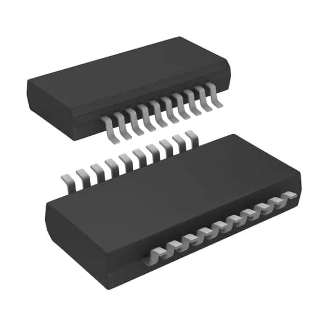
Dual 4-bit inverting buffer — 5V bus isolation in a narrow 20-SSOP
The CY74FCT240ATQCT is a 74FCT-series dual 4-bit inverting buffer with 3-state outputs from Texas Instruments (legacy Cypress Semiconductor portfolio). It provides two independent 4-bit sections, each with its own output-enable control, for isolating or inverting digital buses in 5V systems. The part operates from a 4.75V to 5.25V supply and delivers 32mA source / 64mA sink output current per channel, sufficient for driving moderate capacitive loads on a backplane or buffering address/data lines to a memory array or peripheral interface.
32 mA source, 64 mA sink — what the drive strength buys you
The asymmetric 32mA high-level / 64mA low-level output drive is typical of FCT logic, optimized for driving the higher capacitive load of a bus-low condition. In practice, this means the part can cleanly switch a 50 pF bus at 5V with sub-5 ns propagation delays — enough headroom for 33 MHz to 50 MHz clocked buses without signal-integrity work. The 3-state outputs let multiple devices share a common data bus; the two enable pins (one per 4-bit section) give granular control for byte-wide isolation.
20-SSOP narrow body — land pattern check required
This is the narrow-body SSOP-20, not the wider 5.3 mm or 7.5 mm variants. If your board was laid out for a TSSOP-20 (4.4 mm body) or a standard SOIC-20 (7.5 mm body), the footprint will not match. Verify the land pattern against the 20-SSOP (3.90 mm) mechanical drawing before committing the BOM. Surface-mount reflow profile per J-STD-020 applies;.
The 5V ±5% supply rail is standard for legacy 5V TTL-logic environments; if your system has migrated to 3.3V or lower, this buffer will need a separate 5V rail or a level-shifting alternative.
Active lifecycle, ROHS3 — no end-of-life pressure
For a production BOM line, this means no imminent requalification risk. The 74FCT series has broad installed base, so second-source availability through independent distribution is generally good — but the SN74LVTH16245ADGVR (a 2.7V to 3.6V non-inverting transceiver) is not a functional drop-in replacement due to the supply voltage and logic polarity differences.