4.2 mOhm Rds(on) at 10 V — the conduction-loss floor
The headline spec is the 4.2 mOhm maximum on-resistance at Vgs = 10 V and 18 A — this sets the conduction loss floor for a synchronous rectifier or load switch. The 35 nC typical gate charge at 10 V keeps the gate-drive current moderate for switching frequencies up to a few hundred kilohertz.
60 A drain current — what the thermal budget actually limits
The 60 A continuous rating at 25 °C is a package-limited number on a single-layer test board. The real constraint is the 3 W maximum power dissipation at 25 °C ambient (Ta) versus 53 W at the case (Tc). In a real layout with the 8-VSONP exposed pad soldered to a copper plane, the effective current is derated by the junction-to-ambient thermal resistance and the ambient temperature.
Active production, ROHS3, and the 8-VSONP footprint
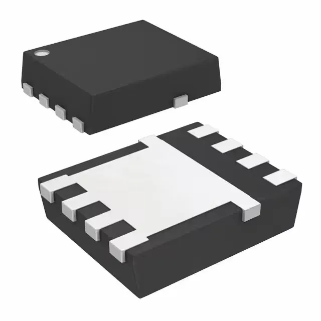
The 8-VSONP (5x6 mm) package has a large exposed thermal pad on the bottom; the PCB layout must include a matching copper land and at least nine thermal vias to pull heat into the inner layers.
