What this PLL clock driver does on your board
The CDCVF25081PWR is a single-chip PLL clock driver from Texas Instruments that takes up to two LVTTL reference inputs and distributes eight synchronized LVTTL outputs at up to 200 MHz. The integrated PLL cleans up jitter on the incoming clock, and the bypass mode lets you feed the reference straight through for test or low-jitter paths where the PLL loop would add phase noise. It runs off a 3 V to 3.6 V rail and is rated for the industrial temperature span of -40°C to 85°C, so it fits in outdoor telecom cabinets, factory-floor controllers, and base-station line cards.
The 200 MHz ceiling covers most common clock trees for Ethernet PHYs, FPGAs, and SoCs that need a clean, low-skew copy of a reference. The 2:8 ratio means you can feed two independent clock sources (say, a primary oscillator and a backup) and drive up to eight loads without an external fanout buffer. Because the outputs are LVTTL and the part is non-differential, it pairs naturally with single-ended clock inputs on standard logic and ASICs — no CML or LVPECL termination resistors needed.
PLL bypass — when to use it
The bypass mode (PLL Yes with Bypass) routes the input clock directly to the outputs, skipping the phase-locked loop. Use it during board bring-up to isolate PLL lock issues, or when the incoming clock is already clean and you want to avoid the PLL's loop-bandwidth jitter. It also serves as a fallback if the PLL loses lock — the outputs keep running on the raw reference instead of going silent.
Package and storage
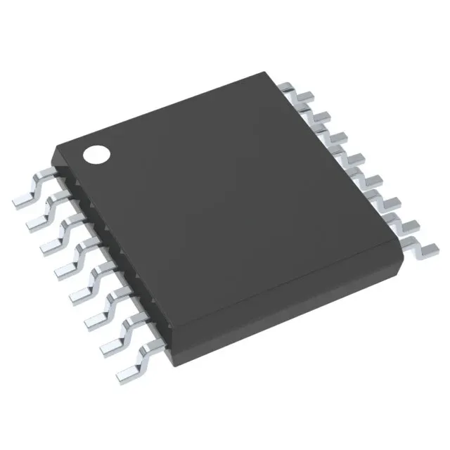
Housed in a 16-pin TSSOP (4.4 mm wide), surface-mount only. The reel ships as Tape & Reel or Cut Tape.