That means TI no longer manufactures this exact order code, and no last-time-buy window is open. If you need a drop-in replacement with the same pinout and charge profile, you will need to evaluate the current-generation single-cell Li-Ion charger family from TI – the BQ24205DGNRG4 uses a 4.1V battery pack voltage, which is less common than the 4.2V standard, so pin-compatibility across the family is not guaranteed without a datasheet cross-check.
Charge current and battery chemistry
This is a constant-current linear charger for single-cell Lithium Ion or Lithium Polymer batteries. The maximum charge current is 500 mA – that sets the charge rate for a single cell. For a 1000 mAh cell, you are looking at roughly a 2-hour charge time. The constant-current profile means no switching noise on the battery line, which matters for noise-sensitive analog loads sharing the battery rail. The battery pack voltage is regulated to 4.1V, not the more common 4.2V. If your design calls for a 4.2V termination voltage, this part will under-charge the cell – you lose about 5-7% of capacity. Check your battery spec: some 4.2V-rated cells accept 4.1V termination with reduced capacity; others require the full 4.2V for proper balancing.
Programmable features and protection
Two programmable features are available: charge current and charge timer. The current is set with an external resistor; the timer provides a safety timeout to terminate charging if the battery never reaches the regulation voltage. Fault protection includes over-temperature and short-circuit – the chip shuts down the pass transistor if the die exceeds the thermal limit or the output is shorted. The supply voltage range goes up to 13.5V max, which covers most 5V USB or 9V wall-adapter inputs. The linear regulator drops the difference between input and battery voltage as heat – at 500 mA with a 5V input and a 3.7V battery, you dissipate about 0.65 W. The exposed pad on the 8-HVSSOP package is essential; without a good thermal via connection to a copper plane, the die will hit the thermal shutdown threshold.
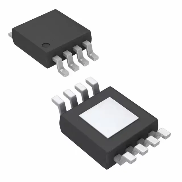
The package is an 8-HVSSOP – essentially an 8-lead MSOP with an exposed thermal pad underneath. The pad is the main heat path, so the PCB footprint must include a matching copper area and thermal vias to an inner ground plane. Without that, the thermal resistance climbs and the over-temperature protection kicks in at lower ambient temperatures. The package is surface-mount, supplied in Tape & Reel, which is standard for pick-and-place. That wide range is typical for TI's charger ICs and gives headroom for designs that see high ambient temperatures or self-heating from the linear regulator.