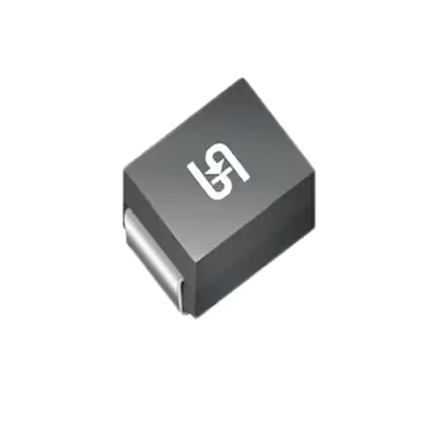
Standoff, breakdown, and clamping — what the voltage hierarchy means
The 1.5SMC91A V7G is a unidirectional TVS diode in the 1.5SMC series — designed to absorb transients on a telecom rail without letting the protected node see more than the clamping ceiling. The reverse standoff of 77.8 V sets the normal operating range: the device sits idle below that, drawing only leakage current. That 125 V clamping maximum is what the downstream load sees during a spike — and with 1500 W peak pulse dissipation, the part handles a substantial event before it degrades. Working backward from the clamping spec: a 125 V clamp at 12.6 A peak pulse means the TVS is clamping aggressively at this rating point, which is exactly what a 1500 W device is designed to do. The 77.8 V standoff sits comfortably below the 86.5 V breakdown minimum, so there is meaningful headroom between the normal rail and the turn-on threshold.
Temperature range and telecom deployment
Junction temperature is what matters for reliability; the 150°C ceiling gives thermal margin for transients that push average dissipation above the derated steady-state limit. The DO-214AB (SMC) package is the industry-standard surface-mount footprint for 1500 W TVS diodes — wide adoption means second-source options are available if the BOM line needs a hedge. Tape-and-reel packaging suits automated placement in high-volume telecom board assembly.
Active status and sourcing posture
Telecom is the stated application category, and the unidirectional polarity is correct for DC rail protection on a positive-going transient path. Power Line Protection is flagged No — this part is not positioned for AC mains crowbar protection but rather for DC secondary-side clamping in telecom power distribution.