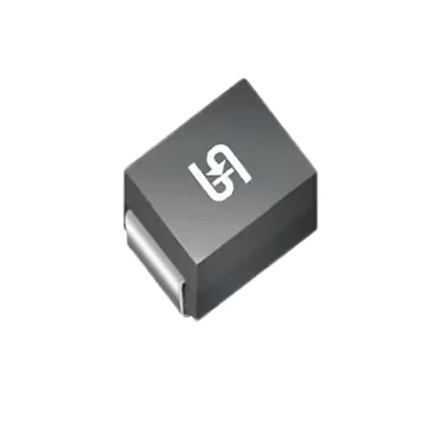
Clamping trio: standoff, breakdown, and the clamp
The 1.5SMC82CA M6G is a bidirectional Zener-based transient voltage suppressor — its three clamping ratings define the protection window a designer works within. The reverse standoff voltage is 70.1 V typical, meaning the device stays off and draws only leakage current during normal line operation. Once a surge pushes the line above the minimum breakdown of 77.9 V, the TVS turns on and clamps the peak fault current to 113 V maximum at the rated 13.9 A peak pulse (10/1000 µs waveform).
1500W peak pulse — what the rating means for transient survival
This is the classic telecom/industrial surge waveform: a 10 µs rise and a 1000 µs fall. A faster edge — 8/20 µs lightning surge — delivers the same energy in less time, which can push the clamping voltage higher before the device settles. Budget the clamp voltage at your actual surge waveform, not just the datasheet number, because the dynamic resistance during turn-on changes the let-through voltage on steeper transients. At 13.9 A peak pulse current in that waveform window, this part handles the Class 3 and Class 4 surge levels typical in 48 V telecom rail and industrial control bus protection. For a 24 V rail, the headroom between standoff and clamping is tight — a 113 V clamp on a 24 V nominal bus means downstream circuits must survive that let-through level, so add upstream series resistance or a lower-Vf clamp if the downstream semiconductor is sensitive.
DO-214AB SMC — placement and thermal relief
With a 150°C maximum junction temperature and no explicit thermal pad, board-level thermal design is the path to reliable operation: the cathode pad area and the copper pour under it set the effective thermal resistance. On a 24-hour clamping event, the datasheet derating curve is your guide — the part will survive a transient but not a sustained overvoltage, so upstream coordination with a fuse or PTC is required if the fault can be held. Tape-and-reel packaging puts this part squarely in the automated placement flow. The SMC body is pick-and-place friendly with no coplanarity concern — the flat leadframe sits cleanly on the pad without the tombstoning risk of smaller packages. Verify the MSL rating in the datasheet before reflow if the reel has been open longer than the floor life allows.