What the voltage-clamp chain means for your protection circuit
The 1.5SMC75CA R7G: The 64.1 V reverse standoff (typ) is the working rail the protected node sits at under normal conditions — the TVS stays dormant and presents only a few microamps of leakage. Those three numbers — standoff, breakdown floor, and clamping ceiling — define the protection window completely. The 1.5 kW peak pulse rating (1.5SMC series designation) reflects the 10/1000 µs surge shape the clamping voltage is specified at. Faster transients (8/20 µs) will draw higher peak currents before reaching the same clamping voltage; the datasheet curve is what governs that relationship for line-conducted or inductive kickback environments. Junction temperature is rated to 150°C — well above the 125°C ceiling common across competing 1.5 kW TVS families. For a TVS that may absorb a surge and self-heat toward its thermal limit, that 25°C of extra headroom means less derating pressure in a warm enclosure or a densely packed board with limited airflow.
Package, mounting, and what 1.5SMC75CA R7G does in the BOM
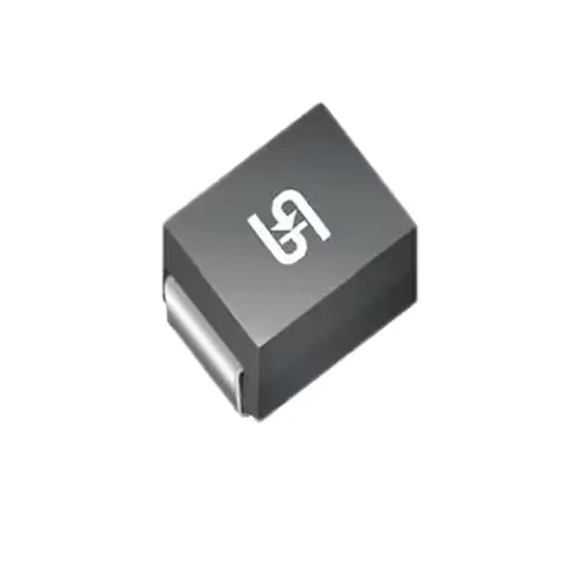
DO-214AB (SMC) is a dominant package for 1.5–3 kW TVS diodes on power-supply boards — the wide cathode pad on the bottom directly bonds to the PCB copper for thermal relief. For a bidirectional TVS the polarity marking on the package top identifies pin 1; the layout should keep the trace from the protected node short and direct to the TVS to minimise let-through inductance ahead of the clamp. The part ships on Tape & Reel for automated placement, and the base product number 1.5SMC75 is the family root — siblings at different stand-off voltages in the same series use the same footprint and thermal pad geometry, so a board layout for a 75 V part works across the family if the voltage budget permits.
Active sourcing posture
Listed Active by Taiwan Semiconductor Corporation. Sourced to order through independent distribution — availability and current pricing confirmed at RFQ.