Three voltages that define the protection window
The 1.5SMC75CA M6G: The standoff voltage of 64.1 V sets the continuous working voltage the diode sees in normal operation — it must stay below this to avoid conduction leakage. Below that sits the reverse leakage spec, which is the drain on the protected rail during idle. Breakdown triggers at 71.3 V minimum, which is where the TVS snaps into conduction and begins clamping. The spec is stated as a minimum because the part must guarantee turn-on at this level — a 'typical' figure alone would not be a design floor. The clamping voltage of 103 V at the rated peak pulse current is what the downstream load sees during a transient event. At 15 A through the device the clamp is held at 103 V — any higher clamping voltage means more overstress on the protected IC or rail segment.
1500 W at 10/1000 µs — what that waveform means
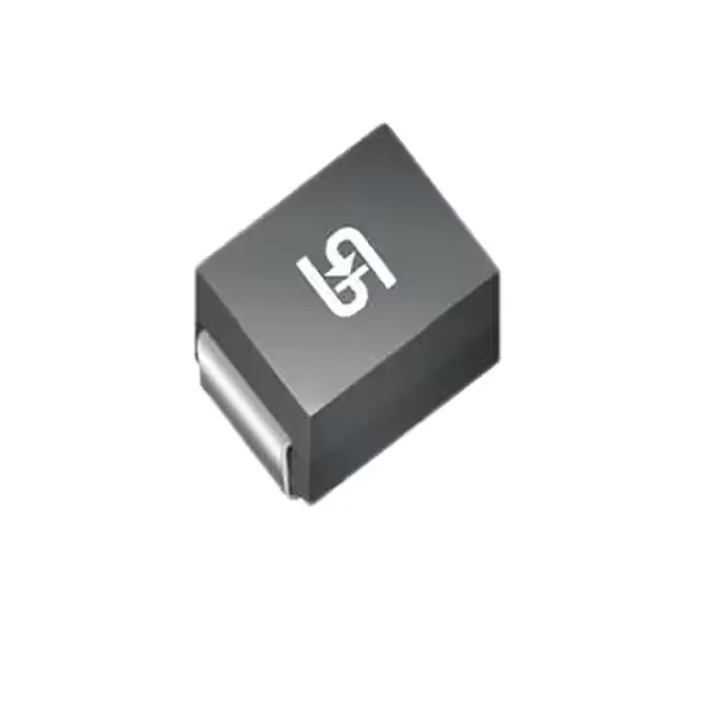
This is a slow, energy-dense transient relative to an ESD event, more representative of inductive kick or power-line surge than a human-body discharge. The 1.5 kW figure is the energy the package can absorb once without degradation. At that pulse the peak forward current is 15 A. For a 64 V rail this puts the clamping action at 103 V — the TVS dissipates the difference between the transient peak and the clamp voltage as heat in the sub-millisecond window. The DO-214AB SMC package handles this with a copper heat-spreading tab; thermal resistance to junction is the limiting factor for repetitive events.
Junction temperature range for bench and field use
Rated to 150 °C junction maximum with a -55 °C low end — the upper bound is set by the Zener avalanche mechanism, which becomes less stable as the junction approaches the thermal limit. A design using this part in a sealed enclosure at 85 °C ambient needs to account for the self-heating of the TVS under fault conditions before the junction hits 150 °C.