The 1.5SMC7.5CA R7G clamps transients at a maximum 11.3 V when conducting 139 A peak pulse (10/1000 µs waveform) — that 11.3 V ceiling is the let-through voltage the downstream circuit must survive. The 7.13 V minimum breakdown marks where the TVS first begins to avalanche, sitting above the 6.4 V standoff so the line idles undisturbed under normal operating conditions. At 1500 W peak pulse the 1.5SMC family handles surges that would destroy a lower-rated TVS in one event — this is the rating that separates it from the 400 W and 600 W siblings in the same series, so match it to the actual surge energy budget of the power bus, not just the steady-state voltage.
DO-214AB SMC on tape-and-reel — rework and assembly check
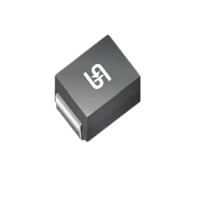
The DO-214AB (SMC) package with surface-mount termination fits the standard pick-and-place footprint for this body size — the twin-barrel anode-cathode configuration means polarity matters at assembly, and the 1.5SMC7.5CA is bidirectional (one channel), so there is no separate polarity pin to track. Shipped on Tape & Reel (TR) — confirm the reel quantity and whether the assembly line's feeder expects 7-inch or 13-inch reel geometry before committing a BOM quantity, since reel size affects kitting workflow even when the part is fully tape-sealed.
The junction temperature range of -55 °C to 150 °C covers both cold-start and thermally-stressed operating environments — a 150 °C Tj ceiling means the part tolerates a significant temperature rise above ambient before derating kicks in, but the actual safe operating area at the board level depends on the thermal impedance between the junction and the mounting pad. Listed as General Purpose with Power Line Protection marked No — this is a signal-level or low-power rail TVS, not a primary power-bus protector, so do not spec it for direct protection across a 48 V or higher power rail without checking the clamping energy against the actual surge scenario.