1500 W peak pulse protection at the 6.4 V standoff rail
The 1.5SMC7.5A R7G: At its core it clamps transient overvoltage to protect downstream circuits — the Zener mechanism avalanche-conducts once the standoff threshold is exceeded, shunting the surge energy away from the load.
What 11.3 V clamping and 139 A peak pulse mean for the protected circuit
The reverse standoff voltage is 6.4 V typical — the working rail can sit below this without the TVS conducting. That 11.3 V ceiling is what the downstream IC or power rail sees under a surge event — well within the abs-max rating of most 5 V logic families. The 1500 W peak pulse power rating defines the energy the device can absorb during the surge event without degradation. The 10/1000 µs waveform is the standard telecom and industrial test pulse — it is slower than an 8/20 µs lightning surge but longer in duration, which tests the device's thermal recovery between pulses in repeated-event applications.
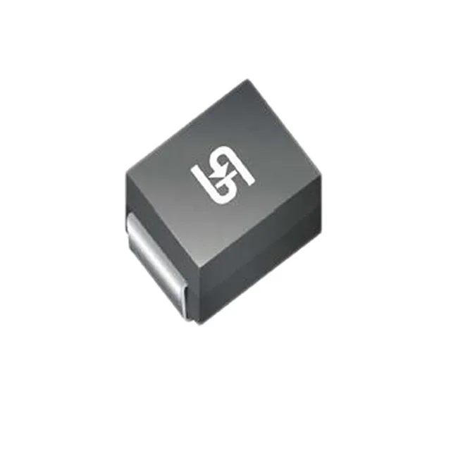
DO-214AB SMC package for surface-mount board assembly
The DO-214AB (SMC) package is the standard outline for 1.5–3 kW TVS diodes — the cathode bar in the centre of the package is the thermal and electrical reference. The part mounts flat to the PCB; the exposed top surface and the cathode pad underneath carry the surge current during clamping, so a solid solder joint and adequate copper plane area under the device matter more than the package outline itself. Operating junction temperature runs from -55°C up to 150°C — the wide span covers both cold-start outdoor enclosures and thermal cycling in equipment without active cooling. The general-purpose rating means it is not AEC-Q qualified, so for automotive-grade protection circuits the datasheet should be reviewed for the specific test conditions before specifying into a safety-critical rail.