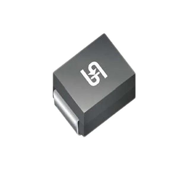
What the 1.5SMC62A V7G is
The standoff rating of 53 V means it sits off and invisible on a 48V telecom bus until a surge appears; the 85 V clamping ceiling protects downstream silicon at 18 A peak pulse (10/1000 µs waveform).
Clamping and standoff — what the voltage figures mean
Reverse standoff of 53 V is the DC working voltage the diode blocks in normal operation — a 48 V nominal telecom supply has ~10% headroom to that limit. When a surge exceeds the 58.9 V breakdown threshold the device snaps into conduction and clamps the peak at 85 V; the 18 A peak pulse current is the event size the clamping table is indexed to. A larger surge (say 30-40 A) will produce a higher clamping voltage following the VI curve — the datasheet IV characteristic is the document to size against the specific transient waveform in the end equipment.
Thermal and package integration
On the board, the SMC (DO-214AB) package dissipates the clamped surge energy through the cathode tab into the copper pad; adequate pad area is the board-level thermal lever, not the package itself. The surface-mount Tape & Reel orientation suits automated pick-and-place on high-density telecom line cards. Unidirectional only — it protects against positive transients relative to ground. Bidirectional protection requires a different topology (two antiparallel unidirectional devices or a genuine bidirectional TVS).