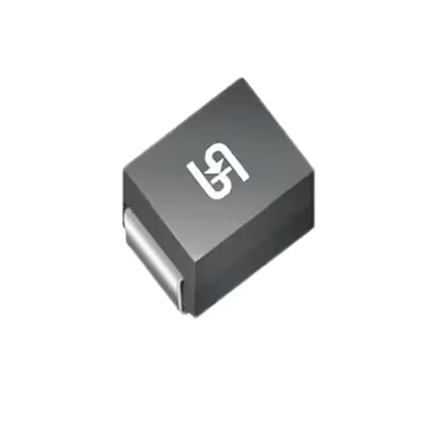
The three voltages that define the protection window
The 1.5SMC6.8A M6G: The reverse standoff of 5.8V sets the working ceiling — the TVS sits idle across the rail up to that level, drawing only leakage current. Transient energy that drives the line above 6.46V (the minimum breakdown) snaps the device into conduction and the clamping characteristic limits the spike to 10.5V maximum at the 150 A peak pulse rating (10/1000 µs waveform). That 10.5V ceiling is what the downstream circuit sees at the height of the event — it is the number that determines whether the protected IC survives the hit.
1.5 kW and 150 A — what the peak ratings mean for board-level protection
1500 W peak pulse power is the product of the clamping voltage and the peak pulse current — it characterises the energy the device can absorb without degradation in the 10/1000 µs window. The 150 A peak pulse current rating tells you the current the clamping path can carry before the device is destroyed; a transient that forces more than 150 A through the TVS at 10.5 V will exceed the 1.5 kW abs-max and damage the part. In practice the source impedance of the transient event sets how much current actually flows — the TVS rating must be above the prospective short-circuit current of the supply line.
150 °C junction limit in a standard SMC package
The 150 °C maximum junction temperature gives real margin for transient thermal events — the clamping action is self-limiting because the IV characteristic curves upward at high current, so the device self-protects to a degree. No power-line protection designation means this part is optimised for signal-line and rail protection in general-purpose circuits, not for direct AC mains clamping.