TVS function and the 1.5SMC family positioning
The 1.5SMC56CA R7G is a bidirectional Zener-type transient voltage suppressor — the CA suffix designates bidirectional polarity, clamping the same threshold in both directions. It slots into the 1.5SMC series, a general-purpose TVS family rated for board-level surge protection on data, signal, and power lines that do not require dedicated power-line certification. The reverse standoff voltage of 47.8 V is the rail voltage the TVS sees during normal operation — the protected line must sit comfortably below this so the Zener remains off and draws only leakage current. When a surge pushes the line above the breakdown threshold, the TVS clamps and diverts up to 20 A away from downstream circuitry.
Protection window — standoff, breakdown, and clamping
Minimum breakdown is 53.2 V — this is the voltage at which the Zener begins conducting in the reverse direction. The protection window opens above this figure and closes at the clamping voltage ceiling of 77 V maximum at the rated peak pulse current. A line sitting at 47.8 V nominal sees a 5.4 V margin to the breakdown floor under normal conditions. The clamping voltage at 20 A peak pulse (10/1000 µs waveform) is 77 V maximum — this is what the downstream IC or transceiver experiences if a surge event reaches the TVS. Selecting the standoff below the circuit working voltage while keeping the clamping ceiling below the downstream absolute maximum rating is the core TVS sizing decision.
Peak pulse power and thermal headroom
Rated 1.5 kW (1500 W) peak pulse power in the 10/1000 µs IEEE/IEC test waveform — this is the standard waveform specifiers use to match the TVS against the application's surge environment (ESD, inductive kick, lightning-induced transient). The 20 A peak pulse current is the companion figure at the 77 V clamping ceiling. Both ratings must be within the application's surge amplitude and duration profile. Derating curves in the datasheet translate peak pulse energy into steady-state junction temperature rise.
DO-214AB SMC package and assembly fit
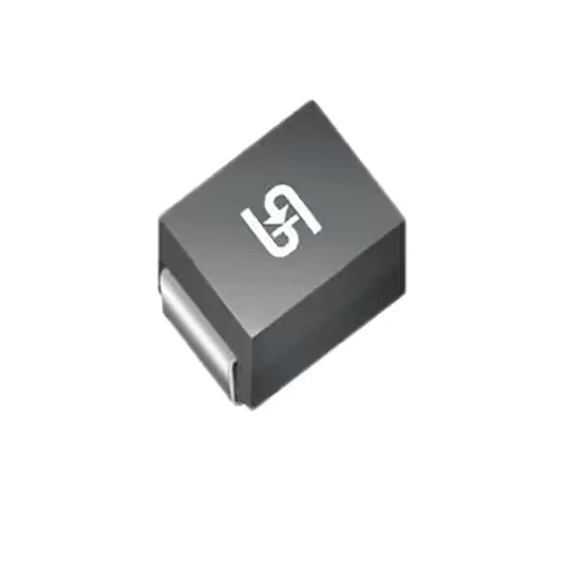
DO-214AB (SMC) is the standard pick-and-place compatible footprint for 1.5–3 kW TVS diodes — the cathode bar on the package top identifies the polarity end. Soldering is reflow-compatible; the thermal pad on the package underside must wet fully to handle the peak pulse energy without dry-joint overheating. Tape and reel packaging suits high-volume SMT assembly.
Sourcing — active production, no successor on record
The base product number 1.5SMC56 identifies the family and voltage index — no official cross-reference or second-source alternative is documented for this specific order code. Quoted to order through independent distribution; availability and lead time confirmed at RFQ.