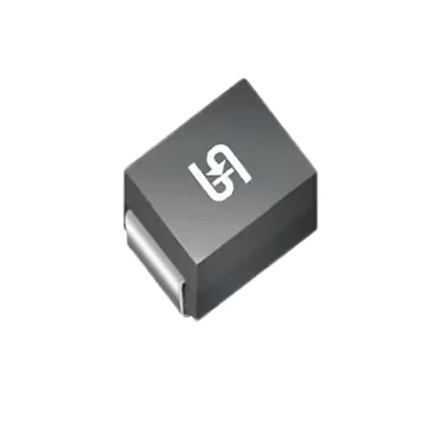
Transient protection fit: 1500 W in a DO-214AB (SMC) package
The 1.5SMC36CA R7G: This defines the transient voltage the downstream circuit must survive — the 49.9 V clamp is the upper bound the protected node sees during an ESD or surge event. Packaged in DO-214AB (SMC), the footprint is a standard surface-mount power package with the cathode band marking for orientation. The tape-and-reel supply format supports automated pick-and-place assembly.
Voltage guard band: standoff, breakdown, and clamp
The three-voltage stack defines the protection window. The 30.8 V reverse standoff is the maximum DC or peak AC voltage the diode blocks without conducting in standby — below this, leakage is negligible and the line sees no loading. The 34.2 V minimum breakdown voltage is where avalanche conduction starts; the circuit must tolerate this level before the clamp engages. The 49.9 V maximum clamp at 31 A is the let-through voltage the protected IC or rail must survive. The 31 A peak pulse current is the corresponding amplitude at the clamp voltage. For shorter pulses (8/20 µs waveform), the peak current capability is higher, but the 10/1000 µs rating is the conservative design anchor for most industrial surge requirements per IEC 61000-4-5. The 'No' on power line protection indicates this is not designed for continuous AC mains overvoltage clamping — it is a transient suppressor for DC rails, signal lines, or low-voltage AC circuits where the transient is brief and the steady-state voltage stays below the standoff.
Active lifecycle — sourcing posture
No compliance documentation (RoHS, REACH, UL, IEC) is detailed in the available record. The series designation and active status suggest standard RoHS compliance by default, but verification against the manufacturer's latest PCN is recommended for formal qualification documentation.