Clamping voltage and pulse current define the rail protection ceiling
The 1.5SMC100A R7G clamps at 137 V maximum when hit with an 11.4 A peak pulse (10/1000 µs waveform). That 137 V ceiling is what the downstream circuitry sees — the TVS absorbs the surge energy and holds the line below the absolute maximum rating of the protected device. Peak pulse power rating is 1500 W (1.5 kW) for the standard 10/1000 µs pulse. This is the energy-handling budget for a single transient event; repetitive surges need derating per the pulse repetition curve in the datasheet.
Standoff and breakdown bracket the operating rail voltage
Reverse standoff voltage is 85.5 V typical — the TVS draws negligible leakage below this level. Breakdown starts at 95 V minimum, so the part sits across an 80–85 V nominal DC rail without conducting in steady state. Single unidirectional channel means the cathode marks the protected rail; the anode connects to ground. For AC or bidirectional clamping, two devices back-to-back cover both polarities.
Junction temperature range and package integration
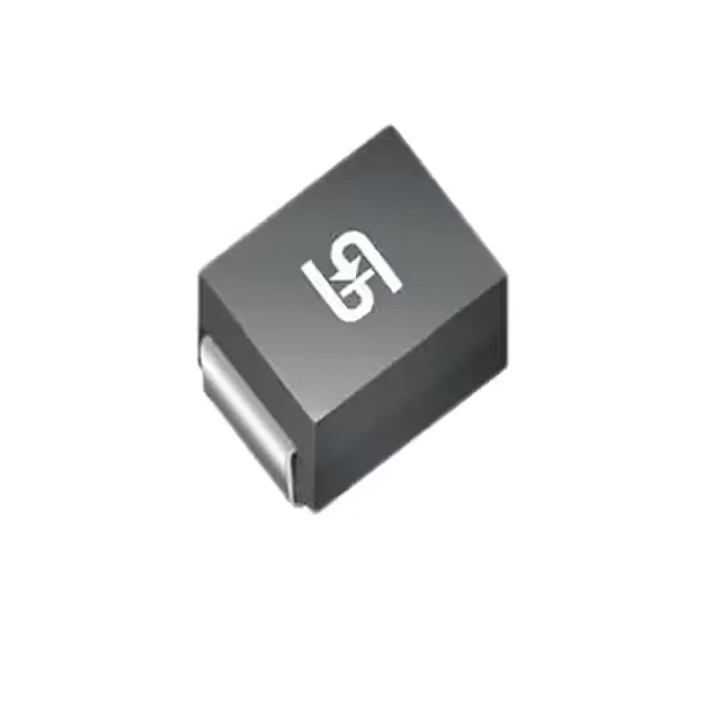
The 150°C upper limit is the silicon junction, not the case; board-level thermal management matters for repetitive pulse duty. DO-214AB (SMC) package, standard surface-mount footprint shared across the 1.5SMC series. The copper pad area under the package sets the thermal impedance for pulse dissipation — a solid ground-plane connection on the cathode tab improves surge current handling.
Active lifecycle and sourcing posture
This part is suitable for ongoing production and new designs.